


Software architecture relies heavily on visual modeling to communicate complex structures. When organizing a system, two primary tools stand out in the Unified Modeling Language (UML) ecosystem. These are the UML Class Diagram and the UML Package Diagram. Each serves a distinct purpose in how developers and architects visualize, document, and maintain codebases. Understanding the specific utility of each diagram type is essential for effective system organization. This guide explores the nuances between these two modeling artifacts to help you choose the right tool for your design needs.
📊 Understanding the UML Class Diagram
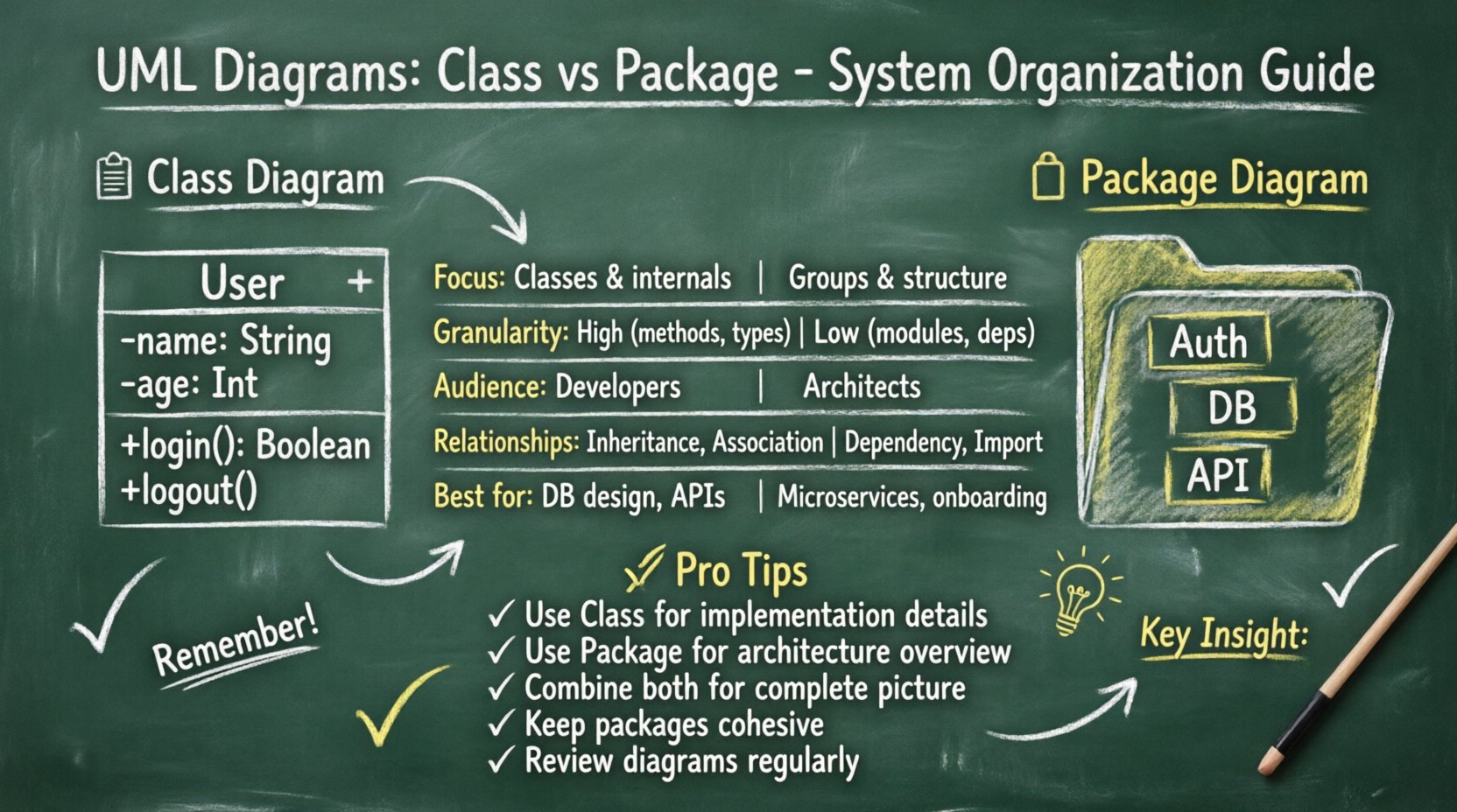
The Class Diagram is the most widely used diagram in UML. It focuses on the static structure of a system by describing the system’s classes, their attributes, operations, and the relationships among objects. In the context of system organization, the class diagram provides a granular view. It details how individual units of code interact at the object level.
Core Components
- Classes: Representations of objects that encapsulate state (attributes) and behavior (methods).
- Attributes: Variables that define the state of a class instance.
- Operations: Functions or methods available to interact with the class data.
- Relationships: Connectors showing how classes depend on or inherit from one another.
Granularity and Detail
Class diagrams operate at a high level of detail. They are designed for software engineers who need to understand implementation specifics. When organizing a system using class diagrams, the focus is on:
- Defining interfaces and contracts between modules.
- Specifying data types and constraints.
- Visualizing inheritance hierarchies and polymorphism.
- Mapping associations, aggregations, and compositions.
This level of detail is invaluable during the implementation phase. It ensures that developers have a clear blueprint for writing code. However, when the system grows large, a single class diagram can become overwhelming. It often fails to provide a macroscopic view of how major subsystems relate to one another.
📦 Understanding the UML Package Diagram
The Package Diagram offers a different perspective. It is designed to organize elements into groups or packages. In UML, a package is a mechanism for organizing related elements. It functions similarly to a namespace or a directory in a file system. The primary goal of a package diagram is to manage complexity by grouping related classes, interfaces, and other packages.
Core Components
- Packages: Containers that hold a set of related model elements.
- Dependencies: Indications that one package relies on the definitions within another.
- Imports: Mechanisms to make elements from one package visible within another.
- Interfaces: Often grouped within packages to define service contracts.
Abstraction and Hierarchy
Package diagrams operate at a higher level of abstraction. They are less concerned with specific attributes or methods and more concerned with the structural boundaries of the software. When organizing a system using package diagrams, the focus shifts to:
- Defining the top-level architecture of the application.
- Separating concerns into logical modules.
- Managing dependencies between major subsystems.
- Establishing clear boundaries for team ownership.
This view is crucial for architects and technical leads. It allows them to see the forest rather than just the trees. By grouping classes into packages, the system becomes easier to navigate. It reduces the cognitive load required to understand how different parts of the codebase interact.
🔍 Key Differences at a Glance
To clarify the distinctions, we can compare the two diagrams across several dimensions. The following table outlines the primary differences in scope, audience, and function.
| Feature | UML Class Diagram | UML Package Diagram |
|---|---|---|
| Primary Focus | Individual classes and their internal structure | Groups of classes and structural organization |
| Granularity | High (Attributes, Methods, Types) | Low (Modules, Namespaces, Dependencies) |
| Audience | Developers, Implementers | Architects, Project Managers, Stakeholders |
| Relationship Type | Inheritance, Association, Aggregation | Dependency, Import, Access |
| Complexity | Can become cluttered in large systems | Designed to manage complexity via grouping |
| Use Case | Database design, API contract definition | Subsystem layout, Module dependency mapping |
🛠️ When to Use Class Diagrams
Selecting the right tool depends on the specific phase of development and the problem being solved. Class diagrams are most effective when the focus is on the internal logic of a component.
1. Detailed Design Phase
During the detailed design phase, the architecture is already set. The team needs to define exactly what data is stored and how it is processed. Class diagrams facilitate this by:
- Specifying data types for every variable.
- Defining the exact signatures of methods.
- Clarifying access modifiers (public, private, protected).
- Documenting business rules embedded within logic.
2. Database Schema Design
Class diagrams often map directly to database schemas. When organizing data persistence, the relationships defined in the diagram (one-to-one, one-to-many) translate directly to foreign keys and join tables. This ensures that the data model aligns with the application logic.
3. Complex Logic Visualization
If a specific module contains intricate inheritance hierarchies or complex state management, a class diagram is necessary. It helps developers understand the flow of control and the inheritance of behavior without reading raw code.
🏛️ When to Use Package Diagrams
Package diagrams excel when the scale of the project makes individual class diagrams impractical. They are the tool of choice for high-level organization.
1. Microservices Architecture
In distributed systems, defining the boundaries between services is critical. Package diagrams can represent these boundaries. Each package might correspond to a specific service or a bounded context. This helps teams understand which service owns which data.
2. Large-Scale Enterprise Systems
Enterprise applications often span thousands of classes. Grouping these into packages (e.g., Core, UI, Business Logic, Data Access) creates a manageable structure. A package diagram shows how these layers interact without overwhelming the viewer with implementation details.
3. Onboarding New Team Members
When a new developer joins a project, a package diagram provides a roadmap. It shows where to find code related to specific functionalities. It answers the question, “Where does the payment processing logic live?” without requiring them to search through hundreds of class files.
🔗 Managing Dependencies and Coupling
One of the most critical aspects of system organization is managing dependencies. High coupling between modules makes a system rigid and difficult to maintain. Both diagram types play a role here, but in different ways.
Package-Level Dependency Management
Package diagrams are the primary tool for visualizing high-level coupling. They show which modules depend on others. If Package A depends on Package B, it implies that changes in B might affect A. By reviewing the package diagram, architects can identify:
- Circular Dependencies: Situations where A depends on B, and B depends on A. This creates a loop that can cause runtime errors or compilation failures.
- Tight Coupling: Packages that rely too heavily on the internal implementation of other packages rather than their interfaces.
- Layer Violations: Situations where a lower-level package depends on a higher-level package, breaking architectural layers.
Class-Level Dependency Management
Class diagrams help manage coupling within a package. They ensure that classes within a module do not become too interdependent. If Class A and Class B in the same package have too many associations, it suggests that the package might be doing too much. This signals a need for further decomposition.
🔄 Combining Both for Effective Architecture
The most robust system organization strategies utilize both diagram types in tandem. They are not mutually exclusive; rather, they complement each other at different levels of abstraction.
Top-Down Approach
Start with the Package Diagram to define the macro structure. Identify the major subsystems and their boundaries. This establishes the skeleton of the system. Once the packages are defined, use Class Diagrams to flesh out the contents of each package.
Bottom-Up Approach
In some refactoring scenarios, you may start with existing code. Analyze the classes to identify natural groupings. Then, create packages to reflect these groupings. Update the Package Diagram to reflect the new structure.
Documentation Consistency
Consistency between the two views is vital. If a class moves from one package to another, the Package Diagram must be updated immediately. Similarly, if a new dependency is added between packages, the Class Diagram should reflect the underlying class interactions. Maintaining this synchronization prevents technical debt and documentation rot.
📈 Best Practices for System Organization
To ensure that your diagrams remain useful over time, follow these established practices.
- Keep Packages Small: A package should be cohesive. If a package contains unrelated functionalities, split it. High cohesion and low coupling are the goals.
- Naming Conventions: Use clear, descriptive names for packages and classes. Avoid abbreviations that are not industry standard.
- Limit Depth: Avoid nesting packages too deeply. A hierarchy deeper than three or four levels becomes hard to navigate.
- Interface Separation: Use interfaces to decouple packages. Packages should depend on abstractions, not concrete implementations.
- Regular Reviews: Treat diagrams as living documents. Review them during code reviews to ensure they match the actual code.
⚠️ Common Pitfalls to Avoid
Even experienced teams make mistakes when modeling systems. Being aware of common pitfalls can save significant time and effort.
- Over-Modeling: Creating diagrams that are too detailed can be as bad as having none. Do not document every single method if the architecture is the priority.
- Ignoring Evolution: Systems change. A diagram created at the start of a project may be obsolete by the end. Plan for updates.
- Mixing Abstraction Levels: Do not put classes and packages in the same view unless necessary. Keep the macro and micro views separate for clarity.
- Ignoring Access Control: When modeling, consider visibility. Public interfaces should be clear, while private implementation details can be hidden in the package view.
📝 Summary
Selecting between UML Class Diagrams and Package Diagrams depends on the level of detail required. Class diagrams provide the necessary precision for implementation and data modeling. Package diagrams offer the necessary structure for high-level architecture and dependency management. By understanding the strengths and limitations of each, you can organize your system more effectively. This leads to code that is easier to maintain, scale, and understand. Use the package diagram to define the boundaries and the class diagram to define the behavior within those boundaries. Together, they form a complete picture of your system’s organization.