


Introduction
In today’s fast-paced software development landscape, clear communication and precise system design are more critical than ever. As Agile methodologies continue to dominate project management approaches, teams are rediscovering the value of visual modeling tools that can keep pace with iterative development cycles. UML Class Diagrams have experienced a remarkable resurgence, particularly as AI-powered visual modeling tools now enable rapid diagram generation, real-time collaboration, and seamless integration with modern development workflows.

This comprehensive guide explores everything you need to know about UML Class Diagrams—from foundational concepts to advanced modeling techniques. Whether you’re a business analyst modeling domain concepts, a developer designing system architecture, or a team lead facilitating cross-functional collaboration, this resource will help you leverage Class Diagrams to create clearer, more maintainable, and better-documented software systems. With the convergence of AI assistance and Agile practices, Class Diagrams are no longer just documentation—they’re living artifacts that evolve alongside your product.
What is a Class Diagram?
In software engineering, a class diagram in the Unified Modeling Language (UML) is a type of static structure diagram that describes the structure of a system by showing the system’s classes, their attributes, operations (or methods), and the relationships among objects.
Purpose of Class Diagrams
-
Shows static structure of classifiers in a system
-
Diagram provides a basic notation for other structure diagrams prescribed by UML
-
Helpful for developers and other team members too
-
Business Analysts can use class diagrams to model systems from a business perspective
A UML class diagram is made up of:
-
A set of classes and
-
A set of relationships between classes
What is a Class
A description of a group of objects all with similar roles in the system, which consists of:
-
Structural features (attributes) define what objects of the class “know”
-
Represent the state of an object of the class
-
Are descriptions of the structural or static features of a class
-
-
Behavioral features (operations) define what objects of the class “can do”
-
Define the way in which objects may interact
-
Operations are descriptions of behavioral or dynamic features of a class
-
Class Notation
A class notation consists of three parts:
-
Class Name
-
The name of the class appears in the first partition.
-
-
Class Attributes
-
Attributes are shown in the second partition.
-
The attribute type is shown after the colon.
-
Attributes map onto member variables (data members) in code.
-
-
Class Operations (Methods)
-
Operations are shown in the third partition. They are services the class provides.
-
The return type of a method is shown after the colon at the end of the method signature.
-
The return type of method parameters is shown after the colon following the parameter name.
-
Operations map onto class methods in code
-

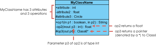
The graphical representation of the class – MyClass as shown above:
-
MyClass has 3 attributes and 3 operations
-
Parameter p3 of op2 is of type int
-
op2 returns a float
-
op3 returns a pointer (denoted by a *) to Class6
Class Relationships
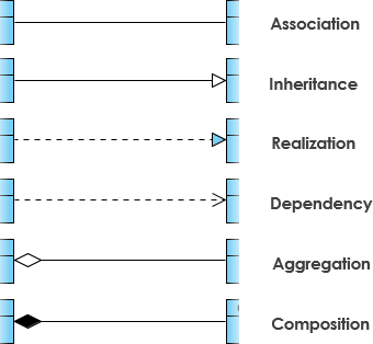
A class may be involved in one or more relationships with other classes. A relationship can be one of the following types:
| Relationship Type | Graphical Representation |
|---|---|
Inheritance (or Generalization):
|
 |
Simple Association:
|
 |
| Aggregation: A special type of association. It represents a “part of” relationship.
|
 |
| Composition: A special type of aggregation where parts are destroyed when the whole is destroyed.
|
 |
Dependency:
|
 |
Relationship Names
-
Names of relationships are written in the middle of the association line.
-
Good relation names make sense when you read them out loud:
-
“Every spreadsheet contains some number of cells”,
-
“an expression evaluates to a value”
-
-
They often have a small arrowhead to show the direction in which direction to read the relationship, e.g., expressions evaluate to values, but values do not evaluate to expressions.

Relationship – Roles
-
A role is a directional purpose of an association.
-
Roles are written at the ends of an association line and describe the purpose played by that class in the relationship.
-
E.g., A cell is related to an expression. The nature of the relationship is that the expression is the formula of the cell.
-
Navigability
The arrows indicate whether, given one instance participating in a relationship, it is possible to determine the instances of the other class that are related to it.
The diagram above suggests that:
-
Given a spreadsheet, we can locate all of the cells that it contains, but that we cannot determine from a cell in what spreadsheet it is contained.
-
Given a cell, we can obtain the related expression and value, but given a value (or expression) we cannot find the cell of which those are attributes.
Visibility of Class Attributes and Operations
In object-oriented design, there is a notation of visibility for attributes and operations. UML identifies four types of visibility: public, protected, private, and package.
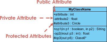
The +, -, # and ~ symbols before an attribute and operation name in a class denote the visibility of the attribute and operation:
-
-
denotes public attributes or operations
-
-
– denotes private attributes or operations
-
# denotes protected attributes or operations
-
~ denotes package attributes or operations
Class Visibility Example
In the example above:
-
attribute1 and op1 of MyClassName are public
-
attribute3 and op3 are protected
-
attribute2 and op2 are private
Access for each of these visibility types is shown below for members of different classes:
| Access Right | public (+) | private (-) | protected (#) | Package (~) |
|---|---|---|---|---|
| Members of the same class | yes | yes | yes | yes |
| Members of derived classes | yes | no | yes | yes |
| Members of any other class | yes | no | no | in same package |
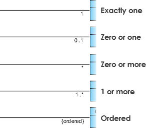
Multiplicity
How many objects of each class take part in the relationships and multiplicity can be expressed as:
-
Exactly one – 1
-
Zero or one – 0..1
-
Many – 0..* or *
-
One or more – 1..*
-
Exact Number – e.g. 3..4 or 6
-
Or a complex relationship – e.g. 0..1, 3..4, 6.* would mean any number of objects other than 2 or 5
Multiplicity Example
-
Requirement: A Student can take many Courses and many Students can be enrolled in one Course.
-
In the example below, the class diagram (on the left), describes the statement of the requirement above for the static model while the object diagram (on the right) shows the snapshot (an instance of the class diagram) of the course enrollment for the courses Software Engineering and Database Management respectively)

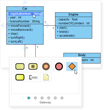
Aggregation Example – Computer and Parts
-
An aggregation is a special case of association denoting a “consists-of” hierarchy
-
The aggregate is the parent class, the components are the children classes

Inheritance Example – Cell Taxonomy
-
Inheritance is another special case of an association denoting a “kind-of” hierarchy
-
Inheritance simplifies the analysis model by introducing a taxonomy
-
The child classes inherit the attributes and operations of the parent class.

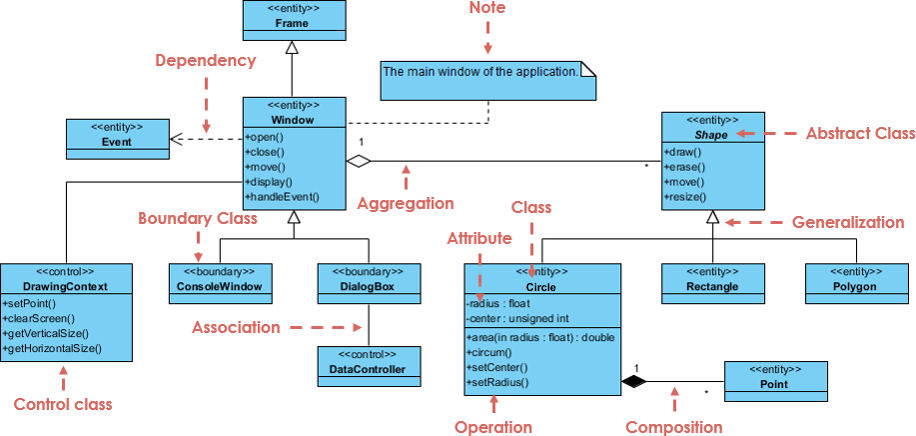
Class Diagram – Diagram Tool Example
A class diagram may also have notes attached to classes or relationships. Notes are shown in grey.

In the example above, we can interpret the meaning of the class diagram by reading through the points as following:
-
Shape is an abstract class. It is shown in Italics.
-
Shape is a superclass. Circle, Rectangle and Polygon are derived from Shape. In other words, a Circle is-a Shape. This is a generalization / inheritance relationship.
-
There is an association between DialogBox and DataController.
-
Shape is part-of Window. This is an aggregation relationship. Shape can exist without Window.
-
Point is part-of Circle. This is a composition relationship. Point cannot exist without a Circle.
-
Window is dependent on Event. However, Event is not dependent on Window.
-
The attributes of Circle are radius and center. This is an entity class.
-
The method names of Circle are area(), circum(), setCenter() and setRadius().
-
The parameter radius in Circle is an in parameter of type float.
-
The method area() of class Circle returns a value of type double.
-
The attributes and method names of Rectangle are hidden. Some other classes in the diagram also have their attributes and method names hidden.
AI-Powered Visual Modeling: The Agile Renaissance of UML
“Since AI-powered visual modeling has become highly relevant to the Agile approach, many teams are coming back to use UML now with very positive feedback.”
The integration of artificial intelligence into visual modeling tools has transformed how teams approach UML Class Diagrams in Agile environments:
Why Teams Are Returning to UML with AI
✅ Rapid Prototyping: AI can generate initial Class Diagrams from natural language requirements, accelerating sprint planning
✅ Living Documentation: Diagrams auto-update as code evolves, maintaining alignment between design and implementation
✅ Collaborative Clarity: Visual models bridge communication gaps between developers, product owners, and stakeholders
✅ Refactoring Support: AI suggests structural improvements and identifies design smells before code is written
✅ Onboarding Acceleration: New team members grasp system architecture faster through interactive diagrams
Multi-Platform AI Support
-
VP Desktop: Generate Class Diagrams via AI and use professional modeling suite for advanced refinement
-
AI Chatbot: Simply describe your domain and let the AI Chatbot generate and touch up your class structures
-
OpenDocs: Embed AI-generated Class Diagrams directly into your OpenDocs pages for live documentation
Specialized Class Diagram Apps
⚡ AI Class Diagram Wizard: Step-by-step assistant for classes, attributes, and operations
🔄 Use Case Studio: Automatically extracts domain classes from behavior descriptions
🚀 Agilien: Bridge User Stories/Epics directly to structural UML models
💾 DB Modeler AI: Generates conceptual Domain Class Diagrams for database design
🏛️ MVC Architecture: Generates specialized Controller Class Diagrams
Explore how to master Class Diagrams with AI:
AI Class Diagram Guide | Full AI Ecosystem
Dealing with Complex Systems: Multiple or Single Class Diagram?
Inevitably, if you are modeling a large system or a large business area, there will be numerous entities you must consider. Should we use multiple or a single class diagram for modeling the problem? The answer is:
-
Instead of modeling every entity and its relationships on a single class diagram, it is better to use multiple class diagrams
-
Dividing a system into multiple class diagrams makes the system easier to understand, especially if each diagram is a graphical representation of a specific part of the system
Perspectives of Class Diagram in Software Development Lifecycle
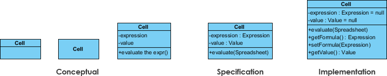
We can use class diagrams in different development phases of a software development lifecycle and typically by modeling class diagrams in three different perspectives (levels of detail) progressively as we move forward:
Conceptual Perspective
-
The diagrams are interpreted as describing things in the real world
-
Represents concepts in the domain under study
-
These concepts will naturally relate to the classes that implement them
-
Language-independent
Specification Perspective
-
Diagrams describe software abstractions or components with specifications and interfaces
-
No commitment to a particular implementation
-
Focus on interfaces of the software, not the implementation
Implementation Perspective
-
Diagrams describe software implementations in a particular technology and language
-
Focus on software implementation details
The UML Class diagram is a graphical notation used to construct and visualize object oriented systems. A class diagram in the Unified Modeling Language (UML) is a type of static structure diagram that describes the structure of a system by showing the system’s:
-
classes
-
their attributes
-
operations (or methods)
-
and the relationships among objects
What is a Class? (Deep Dive)
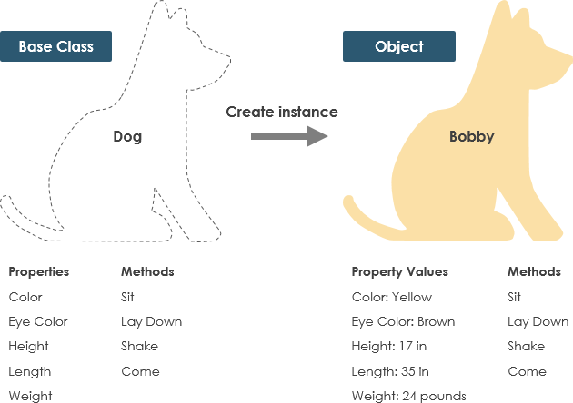
A Class is a blueprint for an object. Objects and classes go hand in hand. We can’t talk about one without talking about the other. And the entire point of Object-Oriented Design is not about objects, it’s about classes, because we use classes to create objects. So a class describes what an object will be, but it isn’t the object itself.
In fact, classes describe the type of objects, while objects are usable instances of classes. Each Object was built from the same set of blueprints and therefore contains the same components (properties and methods). The standard meaning is that an object is an instance of a class and object – Objects have states and behaviors.
Example
A dog has states – color, name, breed as well as behaviors – wagging, barking, eating. An object is an instance of a class.
UML Class Notation (Detailed)
A class represents a concept which encapsulates state (attributes) and behavior (operations). Each attribute has a type. Each operation has a signature. The class name is the only mandatory information.
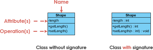
Class Name:
-
The name of the class appears in the first partition
Class Attributes:
-
Attributes are shown in the second partition
-
The attribute type is shown after the colon
-
Attributes map onto member variables (data members) in code
Class Operations (Methods):
-
Operations are shown in the third partition. They are services the class provides
-
The return type of a method is shown after the colon at the end of the method signature
-
The return type of method parameters are shown after the colon following the parameter name
-
Operations map onto class methods in code
Class Visibility
The +, – and # symbols before an attribute and operation name in a class denote the visibility of the attribute and operation.
-
-
denotes public attributes or operations
-
-
– denotes private attributes or operations
-
# denotes protected attributes or operations
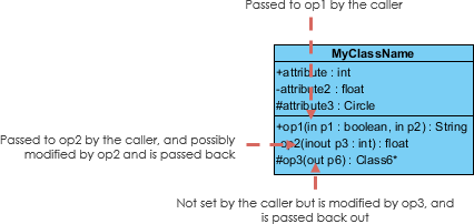
Parameter Directionality
Each parameter in an operation (method) may be denoted as in, out or inout which specifies its direction with respect to the caller. This directionality is shown before the parameter name.
Perspectives of Class Diagram (Visual Guide)
The choice of perspective depends on how far along you are in the development process. During the formulation of a domain model, for example, you would seldom move past the conceptual perspective. Analysis models will typically feature a mix of conceptual and specification perspectives. Design model development will typically start with heavy emphasis on the specification perspective, and evolve into the implementation perspective.
A diagram can be interpreted from various perspectives:
-
Conceptual: represents the concepts in the domain
-
Specification: focus is on the interfaces of Abstract Data Type (ADTs) in the software
-
Implementation: describes how classes will implement their interfaces
The perspective affects the amount of detail to be supplied and the kinds of relationships worth presenting. As we mentioned above, the class name is the only mandatory information.
Relationships Between Classes (Complete Reference)
UML is not just about pretty pictures. If used correctly, UML precisely conveys how code should be implemented from diagrams. If precisely interpreted, the implemented code will correctly reflect the intent of the designer.
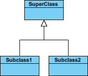
Inheritance (or Generalization)
A generalization is a taxonomic relationship between a more general classifier and a more specific classifier. Each instance of the specific classifier is also an indirect instance of the general classifier. Thus, the specific classifier inherits the features of the more general classifier.
-
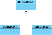
Represents an “is-a” relationship
-
An abstract class name is shown in italics
-
SubClass1 and SubClass2 are specializations of SuperClass
The figure below shows an example of inheritance hierarchy. SubClass1 and SubClass2 are derived from SuperClass. The relationship is displayed as a solid line with a hollow arrowhead that points from the child element to the parent element.
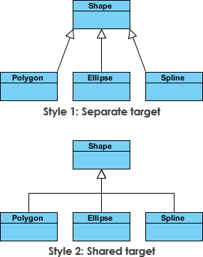
Inheritance Example – Shapes
The figure below shows an inheritance example with two styles. Although the connectors are drawn differently, they are semantically equivalent.
Association
Associations are relationships between classes in a UML Class Diagram. They are represented by a solid line between classes. Associations are typically named using a verb or verb phrase which reflects the real world problem domain.
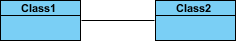
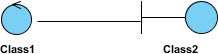
Simple Association
-
A structural link between two peer classes
-
There is an association between Class1 and Class2
The figure below shows an example of simple association. There is an association that connects the <<control>> class Class1 and <<boundary>> class Class2. The relationship is displayed as a solid line connecting the two classes.
Cardinality
Cardinality is expressed in terms of:
-
one to one
-
one to many
-
many to many
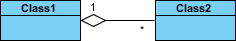
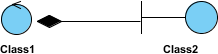
Aggregation
A special type of association:
-
It represents a “part of” relationship
-
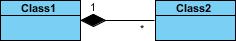
Class2 is part of Class1
-
Many instances (denoted by the *) of Class2 can be associated with Class1
-
Objects of Class1 and Class2 have separate lifetimes
The figure below shows an example of aggregation. The relationship is displayed as a solid line with a unfilled diamond at the association end, which is connected to the class that represents the aggregate.

Composition
-
A special type of aggregation where parts are destroyed when the whole is destroyed
-
Objects of Class2 live and die with Class1
-
Class2 cannot stand by itself
The figure below shows an example of composition. The relationship is displayed as a solid line with a filled diamond at the association end, which is connected to the class that represents the whole or composite.
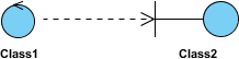
Dependency
An object of one class might use an object of another class in the code of a method. If the object is not stored in any field, then this is modeled as a dependency relationship.
-
A special type of association
-
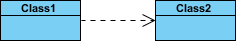
Exists between two classes if changes to the definition of one may cause changes to the other (but not the other way around)
-
Class1 depends on Class2
The figure below shows an example of dependency. The relationship is displayed as a dashed line with an open arrow.
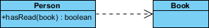
The figure below shows another example of dependency. The Person class might have a hasRead method with a Book parameter that returns true if the person has read the book (perhaps by checking some database).
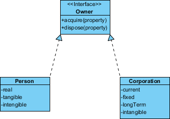
Realization
Realization is a relationship between the blueprint class and the object containing its respective implementation level details. This object is said to realize the blueprint class. In other words, you can understand this as the relationship between the interface and the implementing class.
For example, the Owner interface might specify methods for acquiring property and disposing of property. The Person and Corporation classes need to implement these methods, possibly in very different ways.
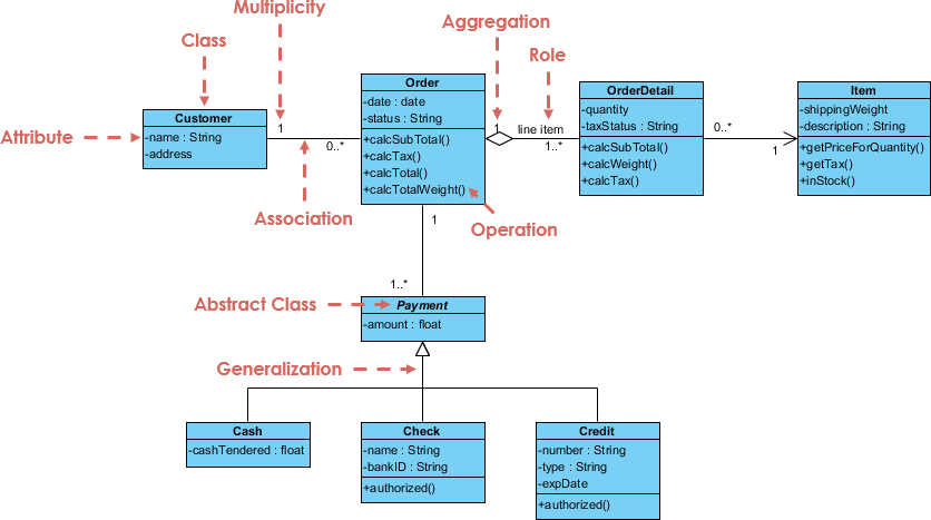
Class Diagram Examples
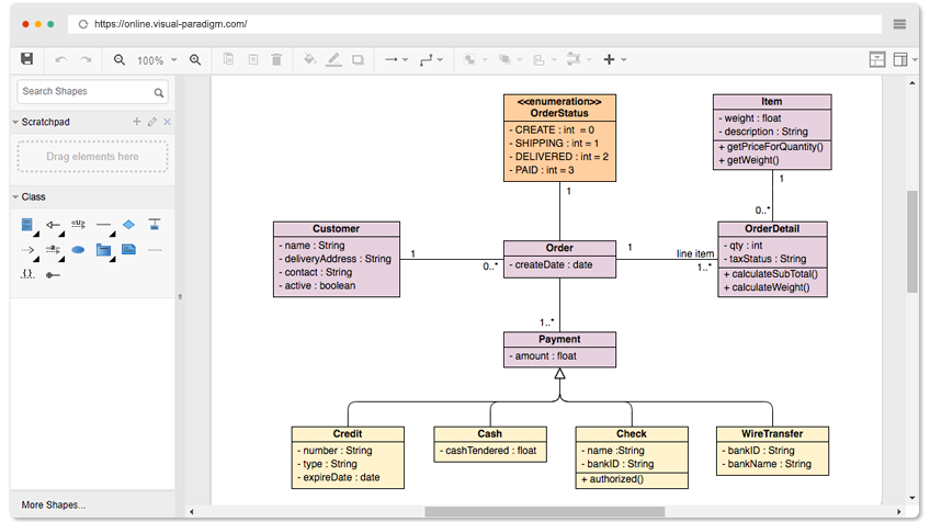
Order System Example
GUI Example
A class diagram may also have notes attached to classes or relationships.
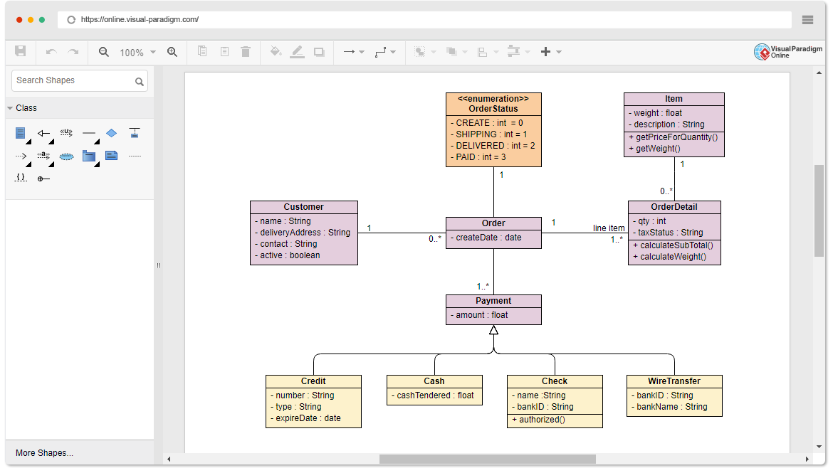
Finding a Free Class Diagram Tool?
Visual Paradigm Online (VP Online) Free Edition is a FREE online drawing software that supports Class Diagram, other UML diagrams, ERD tool and Organization Chart tool. It features a simple yet powerful editor that allows you to create Class Diagram quickly and easily. The free UML editor comes with no ad, no limited period of access and no limitations such as, number of diagrams, number of shapes, etc. You own the diagrams you created for personal and non-commercial purposes.
Speedily Draw Class Diagram
Free UML Software
Draw Class Diagram for personal use for free:
-
No limited number of diagrams and shapes
-
No limited period of access
-
No ad
Draw as many diagrams as you like. Export your drawing into PNG/JPG/GIF/SVG/PDF.
Simple Yet Powerful
UML diagramming can be simple and fun. Here are some of the features of our Class Diagram editor:
-
Drag-to-create shape
-
Well attached connectors (no separate apart)
-
Inline editing of Class Attributes and Operations
-
Draw your own diagrams with your own shapes
-
Hundreds of diagram examples and templates
Impressive Drawing
Position shapes precisely using the alignment guide. Format your Class Diagram with an array of formatting tools: Shape and line format, font style, rotatable shapes, shape alignment and distribution, embed image and URL, shadow effect, etc
Key Features and Benefits
-
Unlimited period of access
-
Unlimited number of diagrams
-
Unlimited number of shapes
-
UML Diagram Tool, ERD Tool, Organization Chart Maker, Floor Plan Designer, ITIL, Business Concept Diagram
-
Can be upgraded to paid editions for more diagram types and features
-
Cross-platform: Windows, Mac, Linux. Compatible with all web browsers
-
Easy to use: Create and connect shapes with drag and drop. Connectors will snap to shapes and never separate apart
-
Apply different formatting options (shape and lines, solid and gradient paint), 40+ connector types, RTF caption, font options, shadow effect, etc
-
Visio drawing and stencil import
-
Draw your own diagrams with your own shapes
-
Easily embed text, external images and web links to diagram
-
Get start quickly with hundreds of diagram examples and diagram templates
-
Print, export and share your work in different formats (PNG, JPG, SVG, GIF, PDF)
-
Google Drive Integration
But Don’t Take Our Word For It
Try it yourself. Just browse the Class Diagram examples below and click Open Diagram to open and edit. You will see for yourself that it is everything we say it is, or perhaps more.
-
Sales Order System
-
Car
-
Telephone
-
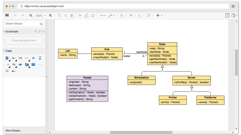
Star-Based LAN
Open Diagram
Conclusion
UML Class Diagrams remain one of the most powerful and enduring tools in software engineering for visualizing, specifying, constructing, and documenting the static structure of object-oriented systems. As this guide has demonstrated, mastering Class Diagrams equips teams with a shared language for discussing system architecture, identifying design flaws early, and maintaining alignment across development phases.
The resurgence of UML in Agile environments—powered by AI-assisted modeling tools—represents a significant evolution in how we approach software design. No longer constrained by manual diagramming overhead, teams can now generate, iterate, and maintain Class Diagrams as living artifacts that evolve alongside code. This synergy between visual modeling and Agile practices enables:
🔹 Faster onboarding through intuitive system visualizations
🔹 Improved communication across technical and non-technical stakeholders
🔹 Proactive design validation before implementation begins
🔹 Automated documentation that stays synchronized with code
🔹 Smarter refactoring guided by structural insights
Whether you’re modeling a simple domain concept or architecting a complex distributed system, Class Diagrams provide the structural clarity needed to build maintainable, scalable software. By embracing modern AI-powered tools and applying the principles outlined in this guide, your team can transform Class Diagrams from static documentation into dynamic catalysts for better software design.
Start small: sketch a conceptual model of your next feature. Iterate with your team. Let AI assist with boilerplate structure. Refine as requirements evolve. The result? A clearer vision, stronger architecture, and software that stands the test of time.
References
- Unified Modeling Language: Wikipedia’s comprehensive overview of UML, the standardized modeling language used for specifying, visualizing, constructing, and documenting software systems.
- Systems Development Life Cycle: Wikipedia’s explanation of the SDLC framework, providing context for where Class Diagrams fit within different development phases.
- Programming Language: Wikipedia’s reference on programming languages, relevant for understanding implementation-perspective Class Diagrams.
- Visual Paradigm Community Edition Download: Free download page for Visual Paradigm Community Edition, an award-winning UML modeling tool supporting all diagram types.
- Visual Paradigm AI Chatbot: AI-powered chat interface for generating and refining UML Class Diagrams through natural language descriptions.
- Visual Paradigm OpenDocs: Tool for embedding AI-generated Class Diagrams directly into live documentation pages.
- AI Class Diagram Wizard: Step-by-step AI assistant for creating classes, attributes, and operations in UML diagrams.
- Use Case Studio: AI tool that automatically extracts domain classes from behavioral use case descriptions.
- Agilien: Platform for bridging Agile User Stories and Epics directly to structural UML models.
- DB Modeler AI: AI-powered tool for generating conceptual Domain Class Diagrams optimized for database design.
- AI MVC Architecture Generator: Specialized AI tool for generating Controller Class Diagrams following MVC architectural patterns.
- AI Class Diagram Generator Guide: Comprehensive tutorial on leveraging AI to accelerate Class Diagram creation in Visual Paradigm.
- Visual Paradigm AI Ecosystem Guide: Overview of the full suite of AI-powered diagramming tools available in the Visual Paradigm platform.
- Visual Paradigm Online Class Diagram Editor: Free online editor for creating and editing UML Class Diagrams with no usage limitations.
- Visual Paradigm Online Pricing: Information on upgrading to paid editions for additional diagram types and advanced features.
- Star-Based LAN Class Diagram Example: Interactive, editable example of a Class Diagram modeling a star-based local area network topology.