


Creating a clear map of how a system should behave is one of the most critical tasks in software development. When stakeholders and developers speak different languages, misunderstandings occur. A Use Case Diagram bridges that gap. It translates raw text requirements into a visual language that everyone can understand. This guide walks you through the process of moving from abstract requirements to a concrete diagram without relying on specific proprietary tools.
Whether you are analyzing a banking app, a hospital management system, or an inventory tracker, the core logic remains the same. You must identify who interacts with the system and what they achieve. This tutorial covers the essential steps to ensure your diagrams are accurate, useful, and aligned with actual business needs.
Understanding the Core Components 🧩
Before drawing lines and boxes, you must understand the building blocks. A Use Case Diagram is not just about pictures; it is about relationships. It focuses on functional requirements.
1. Actors 🧍♂️
An actor represents a role played by a user or an external system. It is not a specific person, but a job title or a system interface.
- Primary Actors: These initiate the process. For example, in a library system, the “Patron” is a primary actor.
- Secondary Actors: These support the process but do not initiate it. For example, a “Payment Gateway” might be a secondary actor helping to process a transaction.
- External Systems: Sometimes, one software system interacts with another. This is also modeled as an actor.
2. Use Cases 🎯
A use case is a specific goal or outcome that an actor wants to achieve. It is a description of a sequence of actions that yields an observable result of value.
- Verb-Object Naming: Always name a use case with a verb and an object. For example, “Place Order” is better than “Order”.
- Granularity: Keep use cases focused. If a use case is too large, it might need to be broken down. If it is too small, it might be merged with another.
3. The System Boundary 📦
The rectangle in a Use Case Diagram represents the system under consideration. Everything inside the box is part of the system. Everything outside is an actor or an external entity.
Gathering Requirements 📋
You cannot draw a diagram until you know what the system should do. This phase is about discovery. It involves talking to people and reviewing documentation.
Interviews and Workshops
Direct communication is the best way to find out what users actually need. Ask open-ended questions:
- What tasks do you perform daily?
- What problems do you face with the current process?
- What information do you need to make decisions?
User Stories
Modern requirements often come in the form of user stories. These follow a simple structure:
“As a [role], I want to [action], so that [benefit].”
These stories are excellent seeds for use cases. For instance, “As a customer, I want to search for products, so that I can find items quickly.” This translates directly to a “Search Products” use case.
Document Analysis
Review existing business process documents. Look for:
- Forms and reports
- Regulatory compliance requirements
- Workflow diagrams
Defining Relationships 📊
Once you have your actors and use cases, you need to connect them. The lines represent relationships. Understanding these connections is vital for a correct diagram.
Association
This is the most basic line. It shows that an actor interacts with a use case. It is a bidirectional link, meaning the actor can trigger the use case, and the use case can send data back to the actor.
Generalization (Inheritance)
This relationship shows that one element is a specialized version of another. In actors, a “Manager” might be a generalization of an “Employee”. In use cases, a “Pay by Card” use case might be a specific type of “Pay” use case.
Inclusion (Include)
This relationship indicates that a base use case must perform the behavior of the included use case. It is a mandatory dependency. If you want to “Register User”, you must “Validate Email”.
Extension (Extend)
This relationship indicates that a base use case may perform the behavior of the extending use case. It is optional and usually happens under specific conditions. For example, “Place Order” can be extended by “Apply Discount” if a coupon code is provided.
| Relationship | Symbol | Meaning | Example |
|---|---|---|---|
| Association | Solid Line | Actor interacts with Use Case | Customer places order |
| Include | Dashed Arrow <<include>> | Mandatory behavior | Print Invoice is required for Checkout |
| Extend | Dashed Arrow <<extend>> | Optional behavior | Print Receipt is optional |
| Generalization | Solid Triangle | Inheritance | Admin is a type of User |
Step-by-Step Diagram Construction 🛠️
Now that you understand the theory, let’s move to the practical steps. This sequence ensures you do not miss critical details.
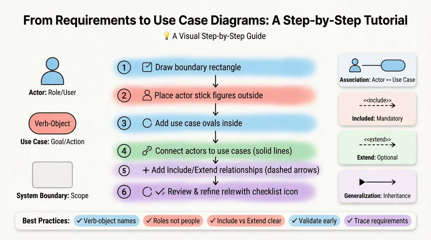
Step 1: Define the System Boundary
Start by drawing a large rectangle. Label it with the name of the system. This sets the scope. Anything outside this box is not part of this specific diagram.
Step 2: Identify Actors
List all the roles that interact with the system. Place them outside the boundary. Use stick figures to represent human actors. Use icons or simple rectangles for system actors.
- Who starts the process?
- Who provides input?
- Who receives output?
Step 3: Draft the Use Cases
Place ovals inside the boundary. Write the verb-object phrase inside each oval. Do not worry about the lines yet. Just list every function the system must perform.
Step 4: Connect Actors to Use Cases
Draw solid lines between actors and the use cases they interact with. Ensure every actor has at least one use case. If an actor has no lines, they are not part of this system’s scope.
Step 5: Identify Relationships (Include/Extend)
Look for common behaviors. If multiple use cases share a step, use an Include relationship. If a use case has optional steps, use an Extend relationship. Place the relationship arrows pointing towards the base use case.
Step 6: Review and Refine
Check your work against the original requirements. Are all requirements covered? Are there any orphaned actors? Is the diagram easy to read? Simplify where possible.
Common Challenges and Solutions 🚧
Even experienced analysts face hurdles. Here are common issues and how to resolve them.
Problem: The Diagram is Too Crowded
If you have too many actors or use cases, the diagram becomes unreadable.
- Solution: Split the diagram into logical groups. Create a high-level diagram for stakeholders and detailed diagrams for developers.
- Solution: Use subsystems. Group related use cases together.
Problem: Actors are Too Specific
Designing a diagram for “John” instead of “Customer”.
- Solution: Always use roles. Roles are reusable and timeless.
Problem: Technical Implementation Details
Adding database tables or UI screens to the diagram.
- Solution: Keep the diagram focused on functionality. Internal implementation details belong in class diagrams or data flow diagrams.
Writing Use Case Descriptions 📄
A diagram is a summary. It does not explain how the use case works in detail. For that, you need a Use Case Description. This document complements the visual diagram.
Key Sections of a Description
- Use Case Name: Clear and concise.
- Actor: Who is performing this action?
- Preconditions: What must be true before starting? (e.g., User must be logged in).
- Postconditions: What is true after completion? (e.g., Order is saved).
- Main Flow: The standard happy path. Step-by-step actions.
- Alternative Flows: What happens if something goes wrong? (e.g., Invalid password).
Validation Techniques ✅
Once the diagram is done, you must verify it. Validation ensures the model matches reality.
Walkthroughs
Walk through the diagram with a stakeholder. Ask them to trace the path from start to finish. If they get confused, the diagram is too complex.
Traceability Matrix
Create a table that links requirements to use cases. This ensures every requirement is addressed.
| Requirement ID | Description | Linked Use Case | Status |
|---|---|---|---|
| REQ-001 | User must login | Authenticate User | Complete |
| REQ-002 | System must calculate tax | Calculate Tax | Pending |
Final Considerations 🌟
Building a Use Case Diagram is a collaborative effort. It requires input from business owners, developers, and testers. The goal is not to create a perfect picture immediately, but to create a shared understanding.
Remember that diagrams evolve. As requirements change, the diagram must change with them. It is a living document, not a static artifact. Regular updates prevent technical debt and ensure the system remains aligned with user needs.
By following these steps, you ensure that your analysis is robust. You move from vague ideas to concrete specifications. This clarity saves time, reduces errors, and leads to better software outcomes. Focus on the what and the who, and leave the how for the implementation phase.
Summary of Best Practices
- Use verb-object names for use cases.
- Keep actors as roles, not individuals.
- Distinguish clearly between Include and Extend.
- Validate with stakeholders early and often.
- Link requirements to use cases for traceability.
With practice, creating these diagrams will become a natural part of your analysis workflow. It transforms complex requirements into a clear visual narrative that drives successful project delivery.