


Systems engineering has reached a point where traditional methods struggle to keep pace with complexity. Engineers often find themselves buried under thousands of pages of requirements, design documents, and verification reports. This fragmentation leads to miscommunication, version control nightmares, and costly errors that surface late in the development lifecycle. Model-Based Systems Engineering (MBSE) offers a structured alternative, shifting the focus from documents to models. At the heart of this methodology lies the Systems Modeling Language (SysML). This guide provides a foundational understanding of SysML without the unnecessary jargon, helping you navigate the transition to model-centric engineering.
What is Model-Based Systems Engineering? 🏗️
MBSE is the formalized application of modeling to support system requirements, design, analysis, verification, and validation activities. It is not merely about drawing pictures; it is about creating a mathematical and logical representation of a system that can be analyzed and interrogated. When you build a model, you are defining the system’s structure, behavior, and requirements in a unified environment.
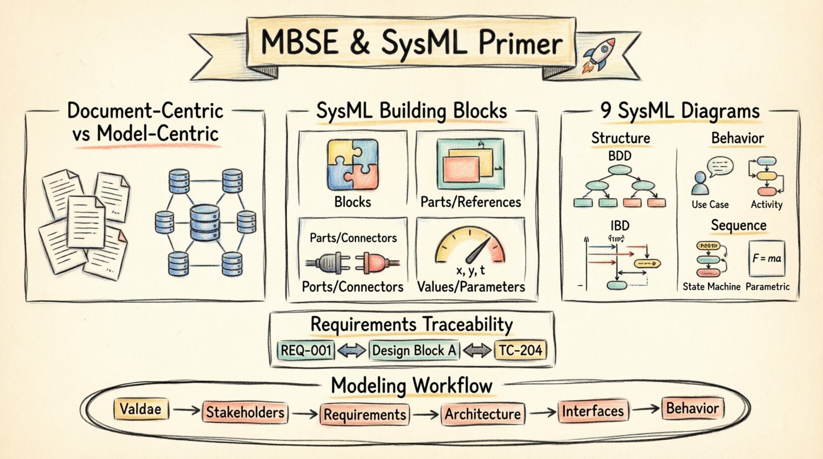
- Document-Centric: Relies on Word, Excel, and PDF files. Information is siloed and hard to cross-reference.
- Model-Centric: Relies on a structured database of model elements. Information is linked and consistent.
The primary advantage of MBSE is traceability. In a document-centric environment, tracing a requirement to a design element often involves manual hyperlinking or text search. In MBSE, these links are explicit, first-class objects within the model. If a requirement changes, the impact on the design can be calculated automatically.
Why SysML? The Standard for Modeling 🌐
Before SysML, engineers used UML (Unified Modeling Language). UML was designed primarily for software development. While it worked for embedded software, it lacked the vocabulary to describe hardware, physical constraints, or performance characteristics effectively. SysML was born as an extension of UML 2.0 specifically for systems engineering.
Key reasons for adopting SysML include:
- General Purpose: It applies to software, hardware, data, and processes.
- Standardized: It is an Object Management Group (OMG) standard, ensuring interoperability across tools and organizations.
- Extensible: It allows for the addition of specific properties without breaking the core syntax.
The Building Blocks of SysML 🧱
Understanding the syntax is the first step. SysML is built upon a set of fundamental building blocks. These are not just visual shapes; they represent logical entities within your system definition.
1. Blocks 🧩
A Block is the fundamental unit of structure. It represents a physical component (like a sensor or a pump) or a logical concept (like a user account or a transaction). Blocks have properties, operations, and constraints.
2. Parts and References 📦
Blocks are composed of other blocks. When a block contains another block, the contained block is a Part. When a block is referenced from another block but is not contained within it, it is a Reference. This distinction is crucial for understanding ownership and interfaces.
- Part: “The Engine is a part of the Car.”
- Reference: “The Car references the Fuel Station.”
3. Ports and Connectors 🔌
Blocks do not exist in isolation. They interact with their environment through Ports. A port is a point of interaction where flows of information, energy, or material occur. Connectors link ports together, establishing the path for these flows.
4. Values and Parameters ⚙️
Blocks have attributes that hold data. These are often called Parameters in SysML. They allow you to define variables such as mass, voltage, or time duration. These values can be used in calculations to verify performance.
The Nine SysML Diagrams 📊
One of the most common questions for beginners is which diagram to use. SysML provides nine distinct diagram types, categorized into two groups: Structure and Behavior. Using the right diagram for the right question is critical for clarity.
| Category | Diagram Type | Primary Purpose |
|---|---|---|
| Structure | Block Definition Diagram (BDD) | Defines the static structure and hierarchy. |
| Structure | Internal Block Diagram (IBD) | Shows internal connections and data flow between parts. |
| Behavior | Use Case Diagram | Describes high-level functional goals. |
| Behavior | Activity Diagram | Models the flow of control and data. |
| Behavior | Sequence Diagram | Shows time-ordered interactions between objects. |
| Behavior | State Machine Diagram | Describes states and transitions of a block. |
| Behavior | Parametric Diagram | Defines mathematical constraints and equations. |
| Requirements | Requirement Diagram | Manages and traces system requirements. |
| Package | Package Diagram | Organizes model elements into namespaces. |
Deep Dive: Block Definition Diagram (BDD) 🔍
The BDD is the backbone of your system structure. It shows the hierarchy of blocks and their relationships. It answers the question: “What is the system made of?” You will see containment relationships (composition), generalizations (inheritance), and associations (links).
Deep Dive: Internal Block Diagram (IBD) 🔄
While the BDD shows the parts, the IBD shows how they connect. It exposes the internal ports and connectors of a block. This is essential for defining interfaces. If you are designing a circuit board, the IBD shows how the resistors connect to the capacitors.
Deep Dive: Parametric Diagram ⚖️
This is often the most misunderstood diagram. It allows you to perform engineering calculations directly within the model. You can define equations like F = m * a and constrain variables. If you change the mass, the force required updates automatically. This supports early feasibility analysis.
Requirements Engineering in SysML 📝
Requirements are the driving force of any engineering project. In SysML, requirements are first-class citizens. They are not just text strings in a Word document; they are model elements that can be linked to structure and behavior.
A SysML requirement element has several properties:
- ID: A unique identifier (e.g., REQ-001).
- Text: The actual statement of need.
- Level: Indicates hierarchy (System, Subsystem, Component).
- Priority: Determines importance.
- Source: Where the requirement originated.
- Verification: How the requirement is tested.
Requirement Relationships 🔗
SysML defines four key relationships for requirements:
- Refine: Breaks a high-level requirement into more detailed sub-requirements.
- Satisfy: Links a requirement to a model element that fulfills it (e.g., a block or activity).
- Verify: Links a requirement to a test case or verification method.
- Trace: General link between two requirements.
Traceability: The Value of the Model 🔗
Traceability is the ability to follow the lineage of a requirement from its origin to its implementation and verification. In a document-based world, this is a manual, error-prone process. In SysML, it is automatic.
Consider a change in a requirement. In a traditional workflow, an engineer must manually search through documents to find where that requirement is implemented. In MBSE, the model engine knows exactly which blocks, activities, and tests are linked to that requirement. This allows for impact analysis.
The Modeling Process: A Workflow 🔄
Building a model is not a one-time event; it is an iterative process. Here is a typical workflow for a beginner:
- Define Scope: Determine the boundaries of the system. What is in scope, and what is out of scope?
- Identify Stakeholders: Who needs to see the model? Operators, developers, customers?
- Capture Requirements: Create the requirement diagram. Ensure every need is documented.
- Architect the System: Build the Block Definition Diagrams. Define the hierarchy.
- Define Interfaces: Use Internal Block Diagrams to define how parts interact.
- Specify Behavior: Use Activity and State Machine diagrams to define logic.
- Validate: Run simulations or calculations using Parametric Diagrams.
Common Pitfalls to Avoid ⚠️
Even with a solid understanding of the syntax, beginners often fall into traps that reduce the value of the model. Awareness of these pitfalls can save significant time and effort.
- Over-Modeling: Do not try to model everything at once. Start with the critical paths. A model that is too detailed too early becomes unmaintainable.
- Ignoring Standards: Do not invent your own notation. Stick to the standard SysML semantics. Custom shapes confuse readers and break tool interoperability.
- Disconnected Diagrams: Ensure all diagrams are linked. A diagram with no connections to other elements is just a drawing. If it does not link to requirements or other blocks, it is not a model.
- Tool Dependency: Do not let the tool dictate the method. The methodology comes first. If you model poorly, a better tool will not fix it.
- Skipping Documentation: Models are not self-explanatory. Use annotations and notes to explain complex logic. Leave comments for future engineers.
Integrating with the Development Lifecycle 🔄
MBSE does not exist in a vacuum. It must integrate with the broader software and hardware development lifecycle. This often involves exchanging data with other engineering domains.
Interfaces with Software Engineering
Software teams often use UML for code generation. SysML can integrate with this by mapping system blocks to software classes. However, care must be taken to ensure the semantics match. SysML defines the “what” and “why,” while software engineering defines the “how”.
Interfaces with Manufacturing
For hardware systems, the model must eventually translate into manufacturing instructions. This often involves exporting data to CAD systems. The Block Definition Diagram provides the bill of materials (BOM) which is essential for production planning.
Challenges in Adoption 📉
Transitioning from documents to models is difficult. It requires a cultural shift. Engineers are trained to write reports, not build databases. There is a learning curve associated with the syntax and the mindset.
Organizations often underestimate the time required for training. It is not enough to buy a tool; you must invest in training the team on the methodology. Without proper training, teams revert to old habits, using the tool only for drawing pictures rather than managing logic.
Measuring Success in MBSE 📏
How do you know if your MBSE implementation is working? Look for these indicators:
- Reduced Rework: Fewer design changes late in the project.
- Faster Verification: Automated checks reduce manual testing time.
- Improved Communication: Stakeholders agree on the system definition earlier.
- Complete Traceability: 100% coverage of requirements to design elements.
Conclusion: The Path Forward 🚀
MBSE and SysML represent a maturation of systems engineering. They provide the rigor and structure needed to manage complex systems. For beginners, the key is to start small, focus on the core building blocks, and prioritize traceability over visual complexity. By embracing these concepts, engineering teams can reduce risk, improve quality, and deliver systems that meet their intended purpose.
The journey from document to model is a significant investment, but the return in clarity and control is substantial. As systems grow in complexity, the ability to model them explicitly becomes not just an advantage, but a necessity.