


Model-Based Systems Engineering (MBSE) relies heavily on a standardized language to communicate complex system architectures. SysML (Systems Modeling Language) serves as this foundation. However, distinguishing between syntax and semantics is often a stumbling block for engineers transitioning from traditional documentation to modeling. Syntax refers to the rules of the language, while semantics define the meaning behind those rules. Understanding the difference is critical for creating models that are not just visually correct, but logically sound.
This guide addresses the most frequent inquiries regarding SysML structure and meaning. We will explore how to define relationships, manage requirements, and utilize diagrams effectively without relying on specific tooling features. The goal is to build a robust mental model of the language itself.
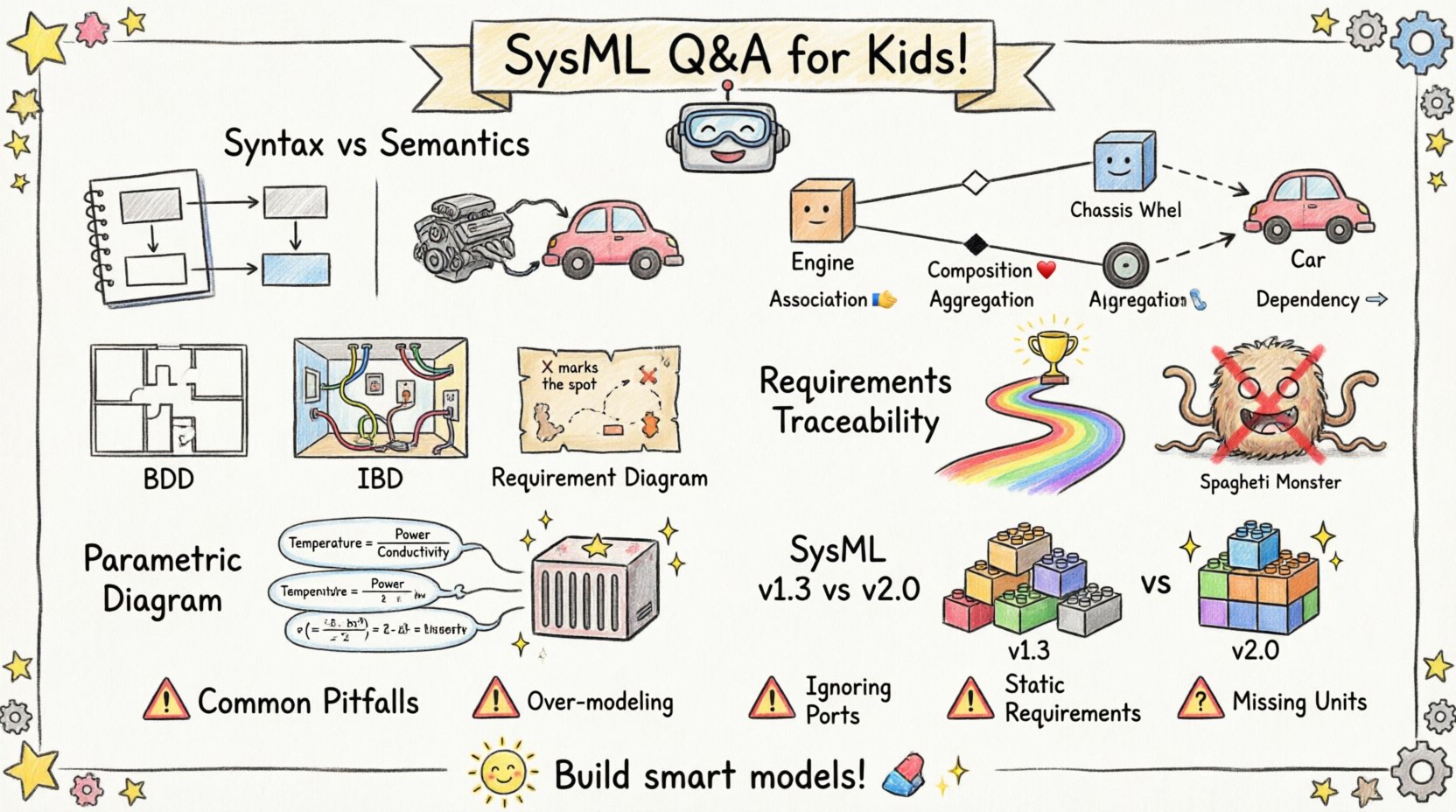
❓ Q1: What is the exact difference between SysML Syntax and Semantics?
Many modelers focus exclusively on the visual aspect, drawing boxes and lines without fully grasping the underlying logic. To model effectively, one must understand the distinction.
- Syntax: This is the grammar of SysML. It dictates what you can draw and how it must look. For example, a Block must be a rectangle. An Association must be a line connecting two classifiers. If you draw a circle for a Block, the modeler violates the syntax.
- Semantics: This is the meaning of the model. It dictates what the drawing represents in the real world. An Association line implies a relationship. A solid diamond implies Composition (ownership). If you draw a line between two blocks but mean to imply they are just communicating, the semantics are wrong even if the syntax is valid.
When you build a model, the syntax ensures the tool accepts the diagram. The semantics ensure the model can be used for analysis, simulation, or verification. A model with perfect syntax but incorrect semantics is useless for engineering validation.
❓ Q2: How do I correctly model relationships between Blocks?
Relationships are the backbone of system structure. Confusion often arises between Association, Dependency, and Generalization. Here is a breakdown of when to use each.
| Relationship Type | Symbol | Meaning (Semantics) | Common Use Case |
|---|---|---|---|
| Association | Solid Line | A structural link indicating that instances of one block can be linked to instances of another. | Connecting a Engine to a Chassis. |
| Composition | Solid Diamond | A strong form of association where the part cannot exist without the whole. Lifecycle is shared. | Connecting a Wheel to a Car. |
| Aggregation | Open Diamond | A weak form of association. Parts can exist independently of the whole. | Connecting a Professor to a Department. |
| Dependency | Dashed Arrow | A usage relationship. One element needs another to exist or function, but not structurally. | A Software Module depending on a Library. |
When defining these in the modeling environment, always ask: “If I delete the whole, does the part cease to exist?” If yes, use Composition. If the part can be moved to another whole, use Aggregation. If it is just a reference, use Dependency.
❓ Q3: Which Diagrams are essential for System Architecture?
SysML offers nine diagram types. While all have their place, not every project requires all nine. For architecture definition, three are paramount.
- Block Definition Diagram (BDD): This is the primary structural diagram. It defines the blocks, their internal composition, and the relationships between them. It is the blueprint of your system.
- Internal Block Diagram (IBD): This drills down into a single block. It shows the internal ports, connectors, and flow of data or matter. It is the wiring diagram for the block.
- Requirement Diagram: This captures stakeholder needs and traces them to system elements. It ensures traceability from high-level intent to physical implementation.
While Sequence Diagrams and State Machine Diagrams are vital for behavioral modeling, the architecture is anchored in the BDD and IBD. Starting with these ensures your structural integrity is sound before adding behavior.
❓ Q4: How do I handle Requirements Traceability without cluttering the model?
Traceability is often a source of noise. Modelers tend to create links everywhere, resulting in a “spaghetti” model that is difficult to read. To maintain clarity, follow these principles.
- Trace at the Right Level: Do not link requirements to individual ports or signals unless necessary. Link to the Block or Subsystem level. A requirement for “Safety” applies to the entire subsystem, not just one connector.
- Use Constraints: For parametric constraints, use the Constraint Block. This keeps the mathematical logic separate from the structural definition, keeping the BDD clean.
- Group Related Items: If a requirement applies to multiple blocks, create a parent requirement and link the sub-requirements to specific blocks.
By limiting the granularity of your traces, you keep the model navigable. A model that is too dense is often treated as a documentation artifact rather than an engineering asset.
❓ Q5: What is the role of Parametric Diagrams in MBSE?
Parametric Diagrams are often misunderstood as optional. In systems engineering, performance analysis is non-negotiable. This diagram type allows you to define mathematical constraints on your system properties.
For example, consider a thermal system. You have a Block for a Heat Sink. You need to ensure the temperature stays below a threshold. A Parametric Diagram allows you to link equations to the Block properties.
- Constraint Blocks: Define the logic once. For example,
Temperature = Power / Conductivity. - Constraint Properties: Link the Constraint Block to specific properties of your Blocks.
- Variables: Use variables to represent values that can be solved or simulated.
This approach moves your model from a static drawing to a dynamic calculation engine. It allows you to validate design choices against physical laws directly within the model environment.
❓ Q6: Are there differences between SysML Version 1.3 and Version 2.0?
The transition to SysML v2 is a significant shift in the engineering community. While v1.3 is still widely supported, v2 introduces changes that affect how we think about syntax and semantics.
| Feature | SysML v1.3 | SysML v2.0 |
|---|---|---|
| Metamodel | UML-based profile | Native language definition |
| Textual Syntax | Not supported | Textual notation is first-class |
| Integration | Separate diagrams | Unified approach to logic and structure |
| Constraints | Parametric Diagrams | Integrated into the language core |
For current projects, v1.3 remains the standard. However, when planning long-term strategy, consider v2. The v2 syntax allows for more direct expression of logic, reducing the reliance on diagrammatic conventions for complex behaviors. Teams should evaluate their tooling support before committing to v2 workflows.
❓ Q7: What are the most common pitfalls in SysML Modeling?
Even experienced engineers encounter recurring issues. Awareness of these pitfalls helps in maintaining model quality.
- Over-Modeling: Creating models for every single detail. Not every subsystem needs a full parametric diagram. Focus on interfaces and critical constraints.
- Ignoring Ports: In IBDs, connectors must match. A data connector cannot connect to a power port. Mismatched ports are a syntax error that leads to semantic failure.
- Static Requirements: Treating requirements as text documents rather than linked model elements. If the requirement is not linked, it cannot be traced or verified.
- Missing Units: SysML supports units, but they are often ignored. Always define units for properties to prevent calculation errors in parametric diagrams.
Adhering to a modeling standard or guideline document can mitigate these risks. A standard defines which diagrams to use, how to name elements, and the rules for relationships.
🔍 Deep Dive: Semantics of Decomposition
Decomposition is a core concept in systems engineering. In SysML, this is primarily handled through the Block Definition Diagram. However, the semantics of decomposition are often lost.
When you decompose a Block, you are not just splitting it visually. You are defining that the child blocks fulfill the functions or properties of the parent. This relationship implies a Constraint. The sum of the parts must satisfy the whole.
For example, if you have a Power System block, and you decompose it into Battery and Converter, the Power System must still meet the output requirements. The model must reflect that the Battery and Converter together provide the Power System functionality.
Without this semantic link, the model is just a list of parts. The decomposition relationship must carry the expectation that the children inherit the interface constraints of the parent. This is often implemented by defining the interface on the parent and ensuring the children implement it.
🔍 Deep Dive: The Role of Ports and Connectors
Ports and Connectors are the interface mechanism of SysML. They define how blocks interact with their environment.
- Standard Port: Defines a standard interface. It specifies what is available but not how it is connected internally.
- Proxy Port: Used in IBDs to represent an interface on a block that is not yet implemented or is external.
- Connector: Links ports together. It defines the flow of information or matter.
A common error is connecting a block directly to another without ports. This bypasses the interface definition. Always use ports to enforce abstraction. This ensures that internal changes to a block do not break the system, provided the interface remains the same.
This separation of interface and implementation is the key to scalable system engineering. It allows teams to work on different subsystems in parallel. As long as the ports match, the integration can proceed without conflict.
🔍 Deep Dive: Handling Time and Sequence
Systems operate over time. SysML captures this through Sequence Diagrams and State Machine Diagrams. However, the syntax must align with the semantic intent.
In a Sequence Diagram, messages represent interactions. If a message is asynchronous, it should be represented as a dashed line. If it is synchronous, a solid line. This semantic distinction matters for execution and analysis.
Similarly, in State Machine Diagrams, transitions represent events. If a transition is triggered by a timer, the event must be defined as a time event. If it is triggered by an external signal, it must be a signal event. Mixing these up leads to ambiguity in simulation.
When modeling complex behaviors, ensure that the timing constraints are explicit. Do not rely on the visual order of messages to imply timing. Use explicit timing constraints in the model.
🔍 Deep Dive: Verification and Validation
The ultimate goal of SysML is to support Verification and Validation (V&V). The model must be capable of supporting these activities.
Verification: Are we building the system right? This involves checking if the model meets the requirements. Traceability links are the primary tool here. Every requirement must be satisfied by at least one system element.
Validation: Are we building the right system? This involves checking if the system meets stakeholder needs. This often requires simulation or prototyping. Parametric Diagrams support this by allowing performance calculations.
Ensure your model contains enough detail to support these checks. If a requirement is vague, the model cannot verify it. If a constraint is missing, the model cannot validate performance. The model is only as good as the information it contains.
🔍 Deep Dive: Naming Conventions
Consistency in naming is a semantic necessity. A name should be unique within a namespace. It should describe the function or type of the element.
- Blocks: Use nouns. Engine, Pump, Valve.
- Operations: Use verbs. Start, Stop, Calculate.
- Properties: Use nouns describing attributes. Mass, Velocity, Temperature.
Avoid generic names like Part1 or Block2. These provide no semantic value to the reader. Clear naming reduces cognitive load and prevents errors during model interpretation.
Consider using a prefix system for subsystems. Hydro_Pump_01 indicates the domain and the item type. This aids in filtering and searching large models.
🔍 Deep Dive: Version Control for Models
Unlike text documents, models are binary files or complex databases. Version control is essential for managing changes.
- Baseline: Create baselines at major milestones. This allows you to revert to a known state.
- Differentiation: Track changes to specific blocks or requirements, not just the whole model.
- Collaboration: Ensure that team members are not editing the same element simultaneously. Use locking mechanisms if available.
Model management is often overlooked. A versioned model ensures that the engineering history is preserved. This is critical for certification and audit processes.
🔍 Deep Dive: Interoperability
SysML is designed to exchange data. The XMI (XML Metadata Interchange) format allows models to be moved between tools. However, semantic loss can occur during export.
- Check Exports: Always validate the imported model. Some constraints may not transfer correctly.
- Standardize Profiles: Use standard profiles to ensure compatibility.
- Limit Customization: Avoid heavy customization of the metamodel. This reduces interoperability.
Interoperability is key for supply chain engineering. Different vendors may use different tools. A standardized model exchange process ensures that the system definition remains consistent across the enterprise.
🔍 Deep Dive: Training and Competency
Building a model requires skill. Training should focus on the semantics, not just the buttons.
- Concept First: Understand systems engineering concepts before touching the tool.
- Pattern Recognition: Learn common patterns for structure and behavior.
- Review: Conduct regular model reviews. Peer review catches semantic errors that syntax checkers miss.
Investing in competency ensures that the investment in tooling pays off. A skilled engineer can model efficiently. An unskilled engineer can create a model that looks good but fails to function.
🔍 Deep Dive: Future of Modeling
The field is evolving. Model-driven architecture and digital twins are expanding the scope of SysML.
- Digital Twins: Models are linked to physical assets. Data flows between the model and the asset.
- AI Integration: AI may assist in generating models or checking consistency.
- Cloud Modeling: Collaborative modeling in the cloud is becoming standard.
Staying updated on these trends ensures that your modeling practices remain relevant. The core principles of syntax and semantics will not change, but the tools and workflows will evolve.