


Systems engineering is complex. It involves managing requirements, understanding interactions, and ensuring that every component works together as intended. Systems Modeling Language (SysML) provides a standardized way to represent these systems. This guide takes you from zero knowledge to a validated model without relying on specific commercial tools.
What Is SysML? 🤔
SysML is a general-purpose modeling language for systems engineering applications. It is based on the Unified Modeling Language (UML) but extends it to support non-software systems. Whether you are designing a spacecraft, a medical device, or a manufacturing process, SysML helps you visualize, specify, analyze, and verify system requirements.
Unlike traditional documentation, which can become outdated quickly, a SysML model serves as a single source of truth. Changes in requirements automatically reflect in the diagrams and analysis. This approach is central to Model-Based Systems Engineering (MBSE).
Why Use SysML Over Text Documents? 📄
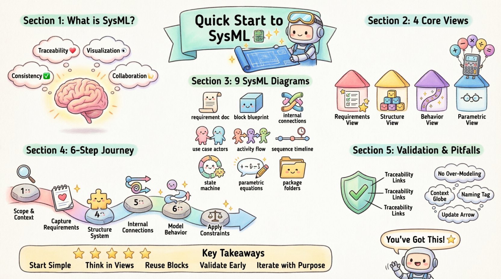
- Traceability: Link requirements directly to design elements.
- Visualization: Complex relationships become clear through diagrams.
- Consistency: Automated checks reduce human error.
- Collaboration: Engineers and stakeholders view the same information.
Core Modeling Concepts 🧱
Before building diagrams, you must understand the fundamental building blocks. SysML organizes system information into four distinct views.
1. Requirements View
Every system starts with what it needs to do. The Requirements diagram allows you to capture high-level goals and break them down into actionable constraints. You can link these requirements to other parts of the model to ensure nothing is left behind.
2. Structure View
This view defines the physical composition of the system. It answers the question: “What is it made of?” Key elements include:
- Blocks: The fundamental units of the system (e.g., a sensor, a motor).
- Properties: Parts that make up a block.
- Relationships: Associations and compositions that define connections.
3. Behavior View
How does the system act over time? The behavior view captures state changes, data flows, and activities. It is essential for understanding logic and control flow.
4. Parametric View
Engineering often involves math. The Parametric diagram allows you to define constraints and equations. This enables quantitative analysis, such as calculating stress limits or power consumption.
The Nine Diagrams of SysML 📊
SysML defines nine specific diagram types. Each serves a unique purpose. Understanding when to use each is critical for a clean model.
| Diagram Type | Primary Purpose | Key Elements |
|---|---|---|
| Requirement Diagram | Define and manage needs | Requirements, Relations |
| Block Definition Diagram (BDD) | High-level structure | Blocks, Relationships |
| Internal Block Diagram (IBD) | Internal structure and flows | Ports, Flows, Connectors |
| Use Case Diagram | System interactions | Actors, Use Cases |
| Activity Diagram | Workflow and logic | Actions, Control Flow |
| Sequence Diagram | Time-based interactions | Lifelines, Messages |
| State Machine Diagram | State transitions | States, Transitions |
| Parametric Diagram | Mathematical constraints | Constraints, Variables |
| Package Diagram | Model organization | Packages, Packages |
Deep Dive: Block Definition vs. Internal Block
Confusion often arises between the Block Definition Diagram (BDD) and the Internal Block Diagram (IBD). Think of the BDD as the blueprint for the house itself (walls, doors, windows). The IBD is the floor plan showing how those rooms connect (pipes, wires, pathways).
Deep Dive: Activity vs. State Machine
Activity diagrams focus on the flow of data and actions. They are best for processes. State machine diagrams focus on the condition of an object. They are best for logic that depends on history or status.
Building Your First Validated Model 🛠️
Creating a model is an iterative process. You do not build it all at once. Follow this logical sequence to ensure validity.
Step 1: Define the Scope and Context
Start with a Use Case diagram. Identify the actors (users, external systems) and the goals they want to achieve. This sets the boundary for your model. Without context, the internal details have no meaning.
Step 2: Capture Requirements
Create a Requirements diagram. List the functional requirements (what the system does) and non-functional requirements (performance, safety, reliability). Ensure every requirement has a unique identifier.
Step 3: Structure the System
Move to the Block Definition Diagram. Break the system into sub-systems. Define the interfaces between them. This is the skeleton of your model.
Step 4: Detail Internal Connections
Use Internal Block Diagrams to define how data and material flow between blocks. Define ports (interfaces) and connectors (paths). This ensures that the physical design supports the logical structure.
Step 5: Model Behavior
Apply Activity and State Machine diagrams. Describe how the system responds to inputs. Define the sequence of events. This validates that the structure can actually perform the required functions.
Step 6: Apply Constraints
Use Parametric Diagrams to verify feasibility. If a requirement states “Battery life must exceed 10 hours,” model the power consumption and capacity. Solve the equations to ensure the design meets the math.
Ensuring Validation and Verification ✅
A model is not finished until it is validated. Validation asks: “Did we build the right system?” Verification asks: “Did we build the system right?”
Traceability Matrices
Traceability is the backbone of validation. You must link requirements to the design elements that satisfy them. If a requirement cannot be traced to a block or a constraint, it is unverified.
- Top-Down Traceability: Link requirements to system elements.
- Bottom-Up Traceability: Link test cases back to requirements.
Consistency Checks
Automated checks can identify errors before human review. Common checks include:
- Are all ports connected?
- Are all requirements satisfied?
- Are there circular dependencies?
Common Pitfalls to Avoid ⚠️
Even experienced engineers face challenges when adopting modeling languages. Be aware of these common issues.
1. Over-Modeling
Creating diagrams for every single detail slows down progress. Focus on the critical paths. Use high-level views for stakeholder communication and detailed views for engineering analysis.
2. Ignoring Context
Models often fail because they ignore the environment. Ensure you model external interfaces and environmental constraints. A system does not exist in a vacuum.
3. Poor Naming Conventions
Clarity is key. Use consistent naming for blocks, ports, and requirements. Ambiguity in names leads to ambiguity in the model.
4. Static Thinking
Systems change. Models should be treated as living documents. Update them as requirements evolve. If the model is not updated, it becomes a barrier rather than a tool.
The Role of Stakeholders 👥
A model is useless if stakeholders cannot understand it. SysML diagrams serve as a communication bridge between different disciplines.
- Management: Needs high-level requirement and use case views.
- Software Engineers: Need detailed state machines and interfaces.
- Mechanical Engineers: Need block structures and parametric constraints.
- Test Engineers: Need clear requirements and verification paths.
Ensure your diagrams are labeled clearly. Use the same terminology across all views. This reduces the cognitive load for everyone reading the model.
Next Steps for Growth 📈
Once you have built your first model, the learning continues. Explore advanced topics such as:
- Simulation: Running dynamic simulations to predict behavior.
- Code Generation: Automatically generating code skeletons from models.
- Integration: Linking the model with project management tools.
Continuous improvement is the key to success. Review your models regularly. Seek feedback from peers. Refine your modeling patterns based on real-world experience.
Summary of Key Takeaways 📝
SysML is a powerful tool for managing complexity. It shifts the focus from documentation to modeling. By following a structured approach, you can create a validated model that stands up to scrutiny.
- Start with Requirements: Define what the system must do first.
- Use the Right Diagrams: Select the view that answers your specific question.
- Trace Everything: Link requirements to design elements.
- Validate Math: Use parametric diagrams for quantitative checks.
- Keep it Simple: Avoid unnecessary complexity.
The journey from zero knowledge to a validated model is achievable with discipline. Focus on clarity, consistency, and traceability. Your models will become the foundation for robust engineering solutions.