


Systems Modeling Language (SysML) has become the backbone of modern Model-Based Systems Engineering (MBSE). As engineering projects grow in complexity, the need for a standardized, visual language to describe system architecture, behavior, and requirements becomes critical. However, diving into SysML can feel like learning a new programming language while simultaneously designing a bridge. This guide provides a structured, practical approach to your first hour of productive modeling.
We will focus on the core concepts that deliver immediate value. You will learn how to structure a system, manage requirements, and visualize behavior without getting lost in the extensive library of diagram types. The goal is not to memorize every rule, but to understand the workflow that prevents ambiguity and miscommunication among stakeholders.
🧠 Understanding the Core Value of SysML
Before drawing a single shape, it is essential to understand what SysML is designed to solve. Traditional documentation relies heavily on text-based specifications. These documents are often static, difficult to update, and prone to inconsistencies. A requirement in a Word document might not match the design in a CAD tool. SysML introduces a single source of truth—a model.
By using SysML, you create a digital representation of the system. This model is executable in the sense that logic and constraints can be validated. It allows teams to catch errors early, before physical prototypes are built. The language extends the Unified Modeling Language (UML) specifically for systems engineering needs.
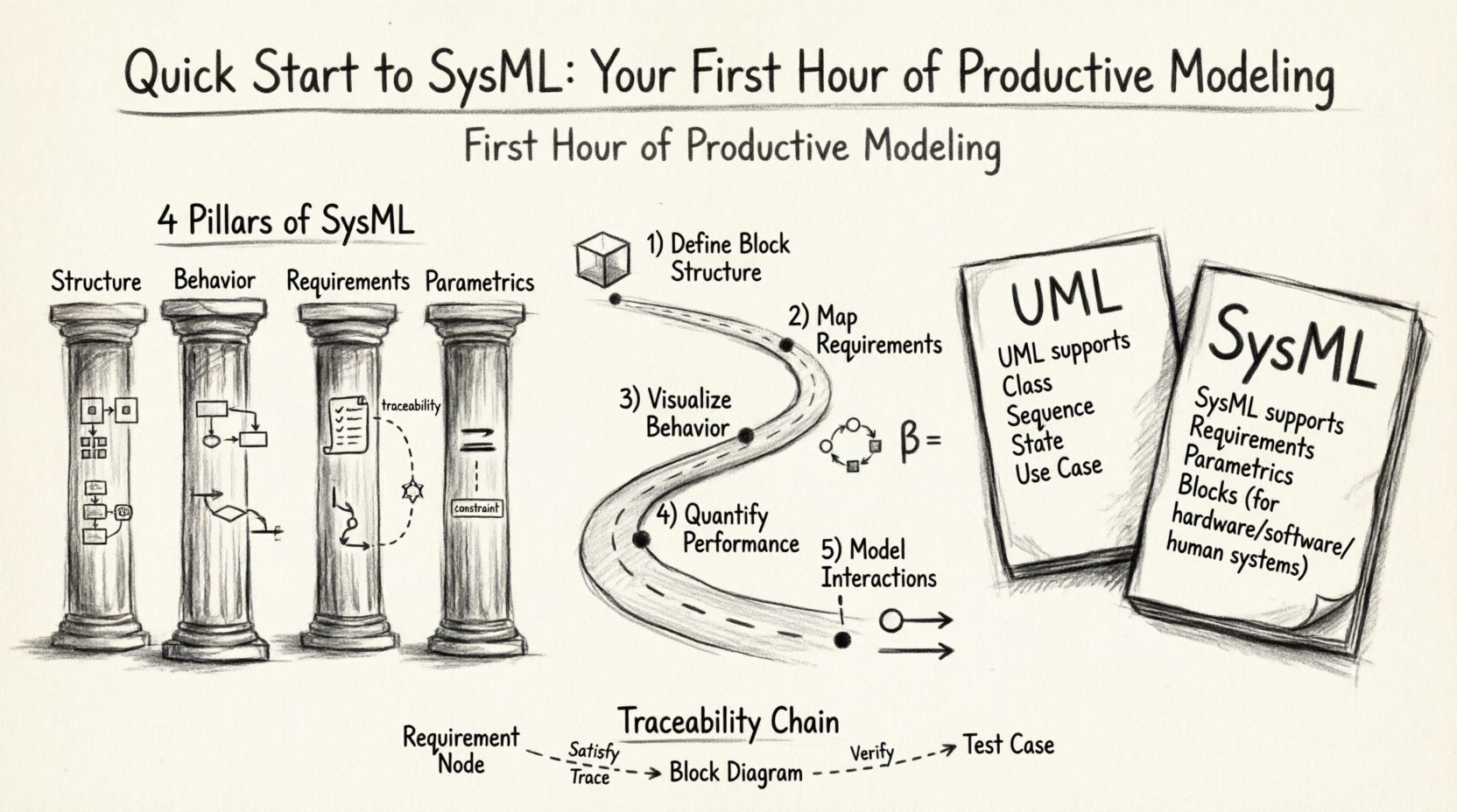
| Feature | UML | SysML |
|---|---|---|
| Primary Focus | Software Systems | General Systems (Hardware, Software, Human) |
| Requirement Management | Not Native | Native Support (Requirement Diagram) |
| Parametric Analysis | Not Native | Native Support (Parametric Diagram) |
| Part Structure | Classes | Blocks (More general) |
The shift from text to model requires a change in mindset. Instead of writing a paragraph describing how a module interacts, you draw the connection. Instead of listing constraints in a table, you define them mathematically within the model. This visual rigor reduces the cognitive load when reviewing complex architectures.
📋 The Four Pillars of SysML Modeling
SysML organizes information into four distinct views. While there are nine diagram types available, they all fall under these categories. Understanding these pillars helps you select the right diagram for the right task during your first hour.
- Structure: Defines the static composition of the system. What parts make up the whole? How do they relate? This is typically visualized using Block Definition Diagrams (BDD) and Internal Block Diagrams (IBD).
- Behavior: Describes what the system does over time. How does it react to inputs? This uses Activity Diagrams and Sequence Diagrams.
- Requirements: Captures stakeholder needs and constraints. This is the traceability backbone of the project, visualized in Requirement Diagrams.
- Parametrics: Deals with quantitative performance. This uses Constraint Blocks and Parametric Diagrams to model equations and physical limits.
For your first session, we will prioritize Structure and Requirements. These provide the skeleton of your project. Behavior and Parametrics can be added as the system definition matures.
⚙️ Step 1: Defining Your System Structure (Block Definition Diagram)
The Block Definition Diagram (BDD) is the most fundamental diagram in SysML. It acts as the index card for your system. Every component, subsystem, and external interface is represented as a “Block”.
Creating Your First Block
Start by defining the root block. This represents the entire system you are modeling. Give it a clear, unique name. Below this root, you will define sub-blocks. These are the major subsystems. Think of a satellite system: the root is “Satellite”, and sub-blocks might include “Power Subsystem”, “Communication Subsystem”, and “Payload”.
- Drag and Drop: Place the root block on the canvas.
- Add Subsystems: Create new blocks that represent the major components.
- Define Relationships: Connect blocks using composition or aggregation.
Understanding Relationships
Relationships define how blocks interact structurally. There are three primary types you need to know initially:
- Composition: A strong “whole-part” relationship. If the whole is destroyed, the parts cease to exist in that context. Example: The Engine is part of the Car.
- Aggregation: A weaker relationship. The parts can exist independently of the whole. Example: A Driver is associated with a Car, but the driver exists without it.
- Association: A general connection indicating a relationship without ownership. Example: A Sensor communicates with a Processor.
When building your structure, avoid creating a flat list of blocks. Aim for a hierarchy. A deep hierarchy allows you to drill down into details later. If a block becomes too complex, create a nested block definition to encapsulate the complexity.
🔗 Step 2: Mapping Requirements (Requirement Diagram)
One of the most powerful features of SysML is the Requirement Diagram. In traditional engineering, requirements often live in spreadsheets or documents. In SysML, they are objects within the model. This allows for direct traceability.
Creating Requirements
Begin by creating requirement nodes. These are distinct from blocks. A requirement represents a condition or capability the system must satisfy. Examples include “The system shall operate in temperatures between -20C and 50C” or “The system shall respond within 100ms”.
- Uniqueness: Assign a unique ID to every requirement (e.g., REQ-001).
- Classification: Mark requirements as “Verification” (testable), “Design” (implementation), or “Concept” (idea).
- Refinement: Use refinement relationships to break a high-level requirement into lower-level details.
Linking Requirements to Structure
The true power lies in linking requirements to blocks. Use a “Satisfy” or “Verify” relationship.
- Satisfy: Used when a lower-level requirement fulfills a higher-level one.
- Verify: Used when a test or check confirms a requirement is met.
- Trace: Links a requirement to a block that implements the functionality.
This creates a traceability chain. If you change a block design, you can instantly see which requirements are affected. If you change a requirement, you can see which parts of the design need updating. This bidirectional link is the core of Model-Based Systems Engineering.
🔄 Step 3: Visualizing Behavior (Activity Diagrams)
Structure tells you what the system is made of. Behavior tells you what the system does. Activity Diagrams are the preferred tool for modeling the flow of control and data within a system. They are similar to flowcharts but with specific SysML semantics.
Key Elements of an Activity Diagram
- Control Flow: Arrows showing the sequence of actions. One action completes before the next begins.
- Object Flow: Arrows showing the movement of data or physical objects between actions.
- Swimlanes: Horizontal or vertical partitions that assign actions to specific actors or subsystems. This clarifies who or what performs the action.
- Decision Nodes: Diamonds that represent a choice (e.g., If Signal is High, then Do A, else Do B).
- Fork/Join: Symbols that allow parallel execution of actions.
Building the Flow
Start your diagram at the “Start Node” (filled circle). Define the initial trigger, such as “Power On” or “Command Received”. Connect actions sequentially. Use decision nodes to handle exceptions or different states. End at the “Final Node”.
When modeling behavior, keep the level of detail consistent. If your blocks represent subsystems, your activities should represent the functions of those subsystems. Do not mix high-level mission flow with low-level electrical signal flow in the same diagram unless necessary. Split them if the complexity grows.
📐 Step 4: Quantifying Performance (Parametrics)
While Structure and Behavior define the logic, Parametric Diagrams define the physics. This is where you ensure the system meets its performance constraints. This is often the most intimidating part of SysML, but you only need the basics to start.
Constraint Blocks
A Constraint Block is a special type of block that contains equations. It does not represent a physical part but rather a mathematical rule. For example, a constraint block might represent “Ohm’s Law” or “Power Consumption”.
- Define Variables: Identify the parameters involved (e.g., Voltage, Current, Resistance).
- Write Equations: Enter the mathematical relationship between these parameters.
Connecting Constraints
To use a constraint, you must connect it to a block. Use a “Constraint Property” to bind the mathematical rule to a specific block. For instance, a “Battery” block might have a constraint property linked to a “Power Budget” constraint block.
This linkage allows for simulation. If you change the capacity of the Battery block, the model can theoretically calculate if the Power Budget is satisfied. While this requires solver integration, defining the constraints correctly is the prerequisite for any future analysis.
🛡️ Step 5: Interaction Modeling (Sequence Diagrams)
Sequence Diagrams are essential for understanding time-dependent interactions between objects. They are particularly useful for defining communication protocols between subsystems.
Visualizing Time
In a Sequence Diagram, time flows from top to bottom. You place the lifelines (the blocks participating in the interaction) at the top. Then, you draw arrows between them to represent messages or signals.
- Synchronous Calls: Solid line with a filled arrowhead. The sender waits for a response.
- Asynchronous Calls: Solid line with an open arrowhead. The sender does not wait.
- Return Messages: Dashed line with an open arrowhead. Indicates the response.
Use Sequence Diagrams to validate the logic defined in your Activity Diagrams. If an activity says “Send Command”, the Sequence Diagram shows exactly which block receives it and when.
📝 Best Practices for Sustainable Modeling
To ensure your model remains useful over time, adhere to these guidelines. A model that is too complex or poorly organized will be abandoned.
- Keep it Simple: Do not model everything at once. Focus on the critical path of your system.
- Consistent Naming: Use clear, descriptive names for blocks and requirements. Avoid abbreviations unless they are standard industry terms.
- Modularity: Group related diagrams into packages. This keeps the workspace organized.
- Review Regularly: Treat the model as a living document. Update it whenever requirements change.
- Validate Traceability: Periodically check that every requirement is linked to at least one design element.
⚠️ Common Pitfalls to Avoid
New users often encounter specific hurdles that slow down progress. Being aware of these can save significant time.
- Over-Modeling: Trying to model every detail in the first hour. Stick to the high-level architecture first.
- Ignoring Requirements: Focusing only on the diagrams and forgetting to link them to requirements. This breaks the traceability loop.
- Mixing Diagrams: Combining structure and behavior in one diagram. Keep BDDs for structure and Activity Diagrams for behavior.
- Neglecting Interfaces: Forgetting to define the ports and flows between blocks. Without interfaces, the model is isolated.
🚀 Moving Forward from Your First Hour
Completing your first hour of modeling is a significant milestone. You have established a structural hierarchy, captured requirements, and defined basic behaviors. The foundation is set.
The next steps involve refining the details. You might add more specific behavior flows, define more complex parametric constraints, or integrate the model with other engineering tools. The flexibility of the language allows you to expand the model as the project evolves.
Summary of Key Actions
To recap the workflow for a successful start:
- Define the Block Structure: Create the root and subsystem blocks using a Block Definition Diagram.
- Link Requirements: Add requirements and connect them to blocks using traceability links.
- Map the Flow: Create an Activity Diagram to show how the system operates over time.
- Review and Refine: Check for consistency and completeness before moving to detailed design.
By following this structured approach, you avoid the common trap of getting lost in technical details too early. You build a clear, communicative model that serves as a reliable guide for the entire engineering team. SysML is a tool for clarity, and with practice, it becomes an extension of your engineering thought process rather than a burden.
Continue to explore the specific capabilities of your modeling environment as you grow. The concepts remain the same, but the implementation may vary. Focus on the logic and the relationships, and the tool will support your work effectively.