


System modeling often feels like navigating a maze of boxes and arrows. While structure diagrams define what a system is made of, behavior diagrams define what a system does. Among these, the State Machine Diagram stands out as the primary tool for capturing the dynamic behavior of a system. It is not merely a flowchart; it is a logic engine that dictates how a system responds to events over time. Understanding the hidden logic within these diagrams is essential for ensuring robust system design.
This guide explores the mechanics of SysML State Machines. We will move beyond basic syntax to examine the architectural decisions that determine system reliability. From nested hierarchies to concurrent regions, the details matter. Precision in modeling translates directly to precision in implementation.
Why State Machines Define System Integrity 🔒
Modern systems are rarely linear. They operate in modes, handle exceptions, and maintain memory of past events. A simple sequence of steps cannot capture the complexity of a system that must pause, resume, or react differently based on its current condition. State machines provide the formalism to describe these conditions.
When modeling a complex system, relying solely on activity diagrams can lead to ambiguity. Activity diagrams show flow, but they do not inherently track state. State machines fill this gap by explicitly defining the status of the system at any given moment. This distinction is critical for safety-critical systems, embedded controllers, and distributed architectures.
Key benefits of using State Machines include:
- Explicit State Definition: Every condition the system can exist in is visually mapped.
- Event-Driven Logic: Triggers for change are clearly associated with transitions.
- History Preservation: The ability to remember previous configurations upon entry.
- Concurrency: Modeling multiple independent behaviors occurring simultaneously.
Core Anatomy of a SysML State Machine 🏗️
To decode the logic, one must understand the fundamental building blocks. A State Machine is composed of states and transitions. These elements interact through events and guards. A clear understanding of each component prevents modeling errors that propagate into the design phase.
States and Initial Points
A state represents a condition during which the system satisfies an invariant, waits for an event, or performs an activity. The journey begins at the Initial Point. This is a solid black circle indicating the starting condition of the system. From here, the first transition must originate to define the entry behavior.
Transitions and Events
A transition connects one state to another. It represents the change of status. For a transition to occur, three conditions must typically be met:
- Event: Something must happen (e.g., a signal arrival, a timer expiration).
- Guard Condition: A boolean expression that must evaluate to true.
- Effect: The action performed during the transition (e.g., logging data, sending a message).
Entry and Exit Actions
States often require specific behaviors upon entering or leaving. These are defined as entry and exit actions.
- Entry Action (/entry): Executed immediately when the state becomes active.
- Exit Action (/exit): Executed immediately before leaving the state.
- Do Activity: An ongoing action performed while the system remains in the state.
Consider a scenario where a system enters a “Calibration” state. The entry action might initialize sensors. The do activity might run a continuous check. The exit action might save the calibration data. Without these distinctions, the timing of operations becomes unclear.
Managing State History with Precision 🕰️
One of the most powerful features in SysML is the ability to track history. When a system leaves a complex state and returns later, does it restart from the beginning, or does it resume where it left off? This decision defines the behavior of the system under intermittent operation.
Shallow History vs. Deep History
History states allow the system to remember its past configuration. There are two distinct types:
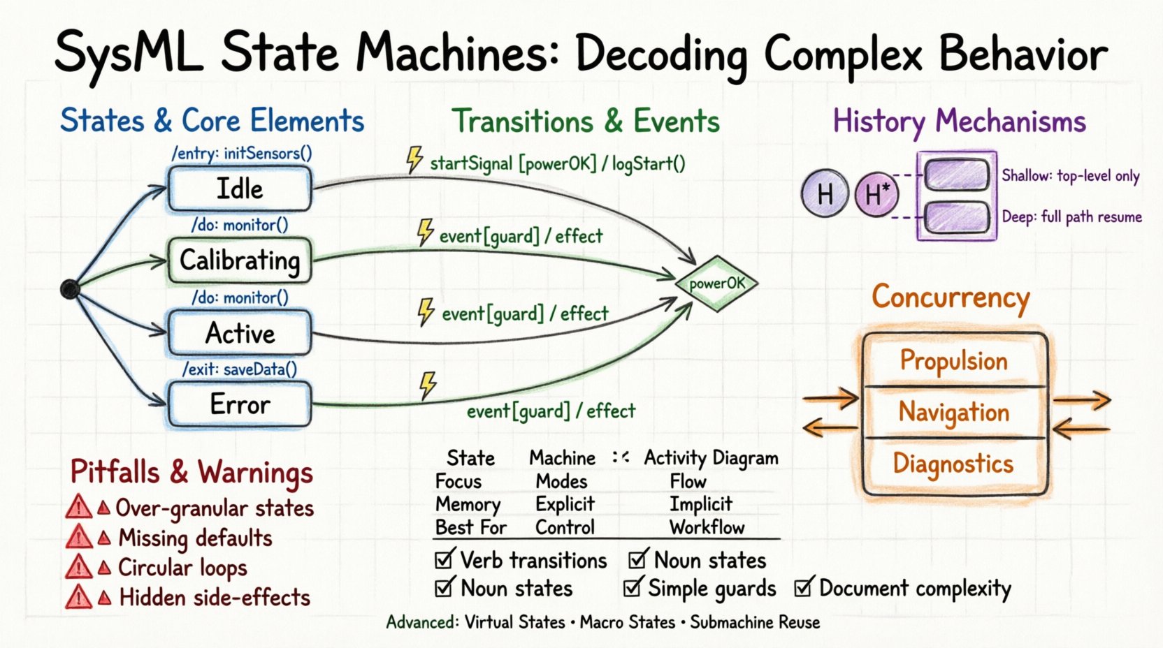
- Shallow History: Remembers the top-level state within a composite state. If the system returns, it enters the last top-level sub-state, ignoring deeper levels.
- Deep History: Remembers the entire nested path. If the system returns, it re-enters the exact sub-state it was in, including all nested levels.
This distinction is vital for systems that undergo complex mode switching. A Deep History state ensures that the context of the operation is preserved, reducing the need for re-initialization routines.
History State Implementation
In the diagram, a history state is represented by a circle with an ‘H’ inside. It is often connected to the state via a transition triggered by an event. The choice between shallow and deep history must be documented clearly, as it impacts the system’s recovery logic.
Concurrency via Orthogonal Regions ⚡
Systems rarely operate in a single dimension. A vehicle system, for instance, manages propulsion, braking, and navigation simultaneously. These behaviors are often independent yet occur within the same system instance. SysML handles this through orthogonal regions.
Split and Join States
To model concurrency, a state is divided into multiple regions separated by a thick bar. This bar acts as a split. When the system enters the composite state, it activates all regions simultaneously. A join bar indicates where these regions synchronize.
Benefits of Orthogonal Modeling
- Decoupling: Different concerns are modeled separately.
- Clarity: Reduces the complexity of a single monolithic state machine.
- Scalability: New concurrent behaviors can be added without disrupting existing logic.
However, concurrency introduces synchronization risks. Designers must ensure that shared resources are managed correctly across regions to prevent race conditions.
When to Use State Machines vs Activity Diagrams ⚖️
Confusion often arises between State Machine Diagrams and Activity Diagrams. Both describe behavior, but their scope differs. Selecting the correct tool depends on the nature of the logic being modeled.
| Feature | State Machine Diagram | Activity Diagram |
|---|---|---|
| Primary Focus | System modes and conditions | Process flow and algorithms |
| State Retention | Explicit (Memory of current state) | Implicit (Variables hold data) |
| Event Handling | Reactive (Driven by external triggers) | Proactive (Driven by data flow) |
| Concurrency | Native support via regions | Supported via forks/joins |
| Best For | Control logic, modes, states | Workflows, data processing |
Use State Machines when the system must wait for events or maintain specific modes. Use Activity Diagrams when the focus is on the sequence of operations or data transformation. Often, a hybrid approach is necessary, where an Activity triggers a State Machine transition.
Common Modeling Pitfalls to Avoid ⚠️
Even experienced modelers can introduce ambiguity. Avoiding common mistakes ensures the model remains a reliable specification.
1. Overly Granular States
Creating a state for every minor variable change leads to a dense diagram that is difficult to read. States should represent significant conditions of the system, not every intermediate data point.
2. Missing Default Transitions
Every state should account for unexpected events. If a specific event is not defined for a state, the system behavior is undefined. Default transitions or general state handling mechanisms should be implemented to manage exceptions.
3. Circular Dependencies
Transitions that create immediate loops without guard conditions can lead to infinite execution. Ensure that loops have clear exit conditions or guard clauses.
4. Ignoring Entry/Exit Effects
Placing logic inside a state without defining entry or exit effects can hide side effects. Always clarify what happens when a state is activated or deactivated.
5. Mixing Control and Data Flow
State Machines are not data flow diagrams. While they can trigger data operations, the primary logic should be control-oriented. Keep data manipulation in Activities or Sequence Diagrams.
Integrating State Logic with Structural Models 🔗
A State Machine does not exist in isolation. It interacts with the structural model of the system. The state machine must reference parts, ports, and signals defined in other diagrams.
Linking to Parts
Transitions often invoke operations on specific parts of the system. For example, a “Start Engine” transition might invoke an operation on the “EngineController” part. This linkage ensures that the behavior is grounded in the physical or logical architecture.
Signal Propagation
Events in state machines are often signals. These signals must be defined as message flows or interface specifications. Ensuring that the signal definitions match the receiver’s expectations is crucial for interoperability.
Best Practices for Clear System Behavior 📝
To maintain clarity and authority in your models, adhere to the following guidelines.
- Consistent Naming: Use action verbs for transitions (e.g., “RequestStart”, “AbortProcess”) and nouns for states (e.g., “Idle”, “Processing”).
- Visual Hierarchy: Use composite states to group related logic. Do not clutter the top level with too many transitions.
- Guard Clarity: Keep guard conditions simple. If a condition is complex, define it as a property or function elsewhere.
- Documentation: Add notes to complex states. Explain the rationale behind specific configurations.
- Review Loops: Regularly review state machines with stakeholders to ensure the logic matches operational requirements.
Advanced Patterns for Complex Logic 🚀
Beyond the basics, SysML allows for patterns that handle sophisticated scenarios.
Virtual States
Virtual states are used to group states without adding a new level of hierarchy. They help organize the diagram visually without affecting the logical transitions. This keeps the diagram clean while maintaining logical grouping.
Macro States
Macro states are composite states that act as a single state in a parent machine. They are useful for abstraction. You can define a complex state machine as a macro state and reference it from a higher-level diagram.
Submachine States
Submachine states allow you to reference an entire external state machine. This promotes reuse. If multiple systems share the same authentication logic, model it once as a submachine and reference it where needed.
Conclusion on Implementation Principles 📊
The logic of a system is embedded in its behavior. By mastering the nuances of State Machines, modelers can create specifications that are robust, maintainable, and clear. The transition from abstract requirements to concrete implementation is bridged by these diagrams.
Focus on clarity over complexity. Use hierarchy to manage depth. Use history to manage memory. Use concurrency to manage parallelism. When these principles are applied consistently, the resulting system behavior is predictable and reliable. The diagram becomes a living document that guides development and testing.
Continue to refine the models as the system evolves. A static model becomes obsolete quickly. A dynamic modeling process ensures that the system logic remains aligned with the operational reality.