


Systems Modeling Language (SysML) provides a robust framework for Model-Based Systems Engineering (MBSE). Within this framework, Parametric Diagrams serve as the primary mechanism for defining mathematical relationships between system properties. However, practitioners often encounter significant hurdles when defining Constraint Expressions and managing Units correctly. These elements are critical for ensuring that simulations yield valid results and that the model accurately reflects physical reality.
This guide addresses the most frequent points of confusion. We will explore the structure of Constraint Blocks, the syntax of expressions, the mechanics of unit conversion, and common pitfalls to avoid. By clarifying these technical details, engineers can build models that are both mathematically sound and maintainable.
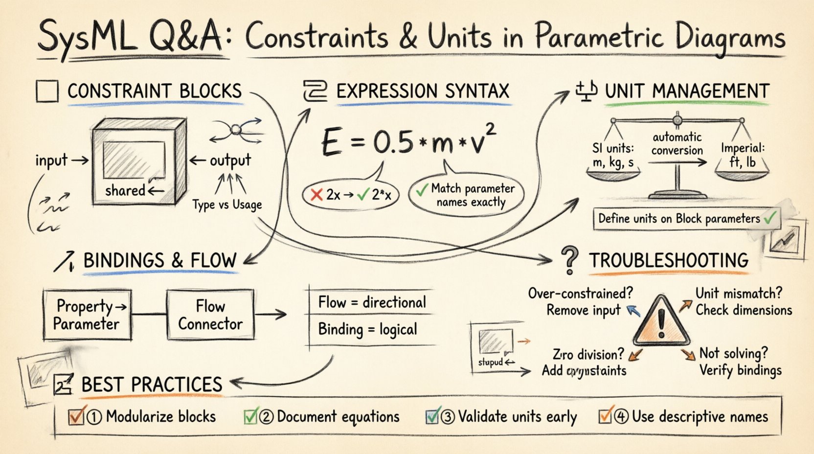
🧱 Understanding Constraint Blocks: The Foundation
Before diving into expressions, one must understand the container that holds them. A Constraint Block is a specialized classifier in SysML. It is not merely a text box; it is a reusable type definition for a mathematical relationship.
- Definition: A Constraint Block defines a set of constraints that can be applied to other elements.
- Parameters: It contains parameters that act as inputs and outputs for the equation.
- Reusability: Once defined, a Constraint Block can be instantiated multiple times across different diagrams.
Confusion often arises regarding the distinction between the Constraint Block Type and the Constraint Usage. The Type defines the logic. The Usage places that logic into a specific context within a diagram.
Defining Parameters within Constraint Blocks
Parameters inside a Constraint Block must be explicitly defined with their direction. This direction dictates how the solver interacts with the value.
- Input: Values provided to the constraint. These are typically known quantities.
- Output: Values calculated by the constraint. These are the results.
- Shared: Values that can be both input and output depending on the solve order.
- Real: The default data type for most engineering parameters.
- Integer: Used for discrete counts or indices.
When modeling a simple relationship, such as Ohm’s Law, the constraint block would define voltage, current, and resistance as parameters. The solver determines which variable is unknown based on the binding and the direction flags.
🧮 Constraint Expressions: Syntax and Logic
The expression is the core logic of the constraint. It describes how the parameters relate to one another. In SysML, this is typically written using a simplified algebraic syntax.
Standard Algebraic Form
Most modeling environments support standard mathematical operators. However, ambiguity can occur with complex equations.
- Equality: Use
=to define the relationship. - Operators: Standard arithmetic (+, -, *, /) is supported.
- Functions: Mathematical functions (sin, cos, sqrt) are generally available.
- Conditionals: Some tools allow if-then logic, though this complicates solver convergence.
Consider the equation for kinetic energy: E = 0.5 * m * v^2. In a constraint block, this translates directly. The challenge lies in ensuring that the parameter names in the expression exactly match the parameter names defined in the block header.
Common Expression Pitfalls
Engineers frequently make mistakes regarding variable scope and syntax. Below are the most common errors.
| Error Type | Description | Resolution |
|---|---|---|
| Variable Name Mismatch | The expression uses a name not defined in the parameter list. | Ensure parameter names in the block header match the expression exactly. |
| Implicit Multiplication | Writing 2x instead of 2 * x. |
Always use the explicit multiplication operator (*). |
| Missing Operators | Writing 2 3 instead of 2 * 3. |
Check for missing symbols between numbers and variables. |
| Undefined Variables | Referencing a property not bound to the constraint. | Ensure all variables are connected via flow connectors. |
⚖️ Handling Units and Dimensions
One of the most complex aspects of SysML modeling is unit management. Physical systems operate in the real world where units matter. A model that ignores units risks producing numerically correct but physically meaningless results.
The Role of the Unit System
Every parameter in a SysML model can be associated with a unit. The modeling environment typically includes a default unit system (often SI units like meters, kilograms, seconds). However, engineers can define custom units or select alternative systems (e.g., Imperial).
- Dimensional Consistency: The solver checks if the dimensions match. You cannot add meters to seconds.
- Conversion: If a parameter is defined as “meters” and another as “kilometers”, the solver handles the conversion automatically.
- Hidden Units: Some parameters are dimensionless (e.g., ratios, angles in radians).
Where to Define Units
There are two primary locations to specify units. Confusion often stems from not knowing which one to use.
- On the Parameter: Define the unit directly on the Constraint Block parameter. This is best for reusable blocks where the unit is intrinsic to the definition.
- On the Property/Link: Define the unit on the flow connector or the property being bound to the parameter. This is best when the context dictates the unit.
Best Practice: Define units on the Constraint Block parameters. This ensures that the constraint logic remains valid regardless of where the constraint is used in the model.
Unit Conversion Logic
When constraints are solved, the solver normalizes all values to a common base unit before performing calculations. This prevents errors caused by mixing incompatible scales.
- Base Units: The solver converts everything to base SI units internally.
- Display Units: The final result is converted back to the user’s preferred display unit.
- Consistency Check: If a constraint requires adding force to mass, the solver will flag an error due to dimensional mismatch.
🔗 Binding Parameters and Flow Connectors
Constraint Blocks are useless if they are not connected to the rest of the model. This connection happens through Bindings and Flow Connectors.
Binding Relationships
A binding establishes a relationship between a parameter in a constraint block and a property in a Block Definition Diagram or another constraint. This tells the solver which value flows into the constraint and which flows out.
- Property to Parameter: Connect a property (e.g., Mass) to a parameter (e.g.,
m). - Parameter to Parameter: Connect the output of one constraint to the input of another.
Flow Connectors vs. Bindings
While similar, they serve different semantic purposes.
| Connector Type | Usage | Example |
|---|---|---|
| Flow Connector | Shows the direction of data or physical flow. | Force flowing into a Mass element. |
| Binding Line | Indicates logical equivalence without direction. | Linking a Property to a Constraint Parameter. |
For parametric diagrams, Flow Connectors are generally preferred as they visually indicate the dependency chain required for solving the system of equations.
❓ Q&A: Resolving Common Confusions
Even with a solid understanding of the theory, specific scenarios often cause roadblocks. Here is a targeted Q&A to address these edge cases.
Q1: What if my constraint is not solving?
If the solver cannot find a solution, check the following:
- Over-Constrained: Too many input values are defined. The system has more equations than unknowns. Remove an input binding.
- Under-Constrained: Too many unknowns. The system has more unknowns than equations. Provide values for more inputs.
- Nonlinear Issues: Complex nonlinear equations may require a specific starting value or range to converge.
- Unit Mismatch: Ensure all parameters have compatible units defined.
Q2: Can I use text strings in constraints?
No. Constraint Expressions are strictly mathematical. They operate on numeric values (Real or Integer). If you need to represent text, use a separate property on the Block and reference it logically, but do not attempt to include it in the algebraic expression.
Q3: How do I handle conditional logic (e.g., if-else)?
Standard algebraic solvers do not handle discrete if-else logic well. It can cause discontinuities that prevent convergence. Instead, use piecewise functions or linear approximations where possible. If discrete logic is required, consider modeling it as a separate state machine rather than a parametric constraint.
Q4: What is the difference between a Block and a Constraint Block?
- Block: Represents a physical part or component with properties and behaviors.
- Constraint Block: Represents a mathematical relationship or rule. It does not exist physically.
You can link a Block to a Constraint Block to apply the math to the physical part.
🛠️ Best Practices for Maintainability
Building a parametric model is not just about making it work today. It is about ensuring it works tomorrow when requirements change. Adhering to these practices will save significant time during future reviews.
1. Modularize Constraints
Do not create a massive constraint block that handles the entire system. Break complex systems into smaller, manageable blocks.
- Create a block for Thermal Dynamics.
- Create a block for Structural Load.
- Create a block for Power Distribution.
This separation of concerns makes debugging easier. If the thermal model fails, you do not need to debug the power model.
2. Document the Logic
Comments within the model are essential. SysML allows for comments attached to constraint blocks. Use these to explain the source of the equation.
- Reference the engineering standard (e.g., ISO-1234).
- Note any assumptions made (e.g., “Assumes constant temperature”).
- Link to external calculation sheets if the equation is too complex for the diagram.
3. Validate Units Early
Check units at every step of development. Do not wait until the final simulation. Define units as soon as you create a parameter. This prevents the “unit drift” that occurs when engineers switch between unit systems halfway through a project.
4. Use Named Parameters
While p1, p2, p3 is easier to type, Force, Mass, Acceleration is easier to read. Always use descriptive names for parameters in constraint blocks. This reduces cognitive load for anyone reviewing the model later.
🔍 Troubleshooting Table: Unit Errors
The following table outlines specific error messages related to units and how to resolve them.
| Error Symptom | Cause | Solution |
|---|---|---|
| Dimension Mismatch | Adding incompatible units (e.g., Length + Time). | Review the equation logic. Ensure physical dimensions align. |
| Undefined Unit | A parameter has no unit assigned. | Assign a default unit or a specific unit from the library. |
| Conversion Error | Attempting to convert between incompatible systems. | Ensure both units belong to the same dimension (e.g., both are length). |
| Zero Division | Dividing by a parameter that resolves to zero. | Check input values. Add constraints to prevent zero division. |
🚀 Moving Forward
Parametric Diagrams are a powerful tool in the SysML arsenal. They bridge the gap between abstract requirements and physical implementation. By understanding the nuances of constraint expressions and unit management, engineers can create models that are not only functional but also trustworthy.
Remember that modeling is an iterative process. Start with simple constraints. Validate them. Add complexity gradually. Do not rush to implement the full system logic before the basic relationships are stable. This disciplined approach ensures that the mathematical foundation remains solid as the model grows.
Focus on clarity, consistency, and documentation. These three pillars will support your work far better than any specific tool feature. With practice, the confusion surrounding these diagrams will diminish, leaving a clear path for systems design and verification.