


Modern software systems often begin with a clear vision but evolve into complex, tangled structures over time. This phenomenon, known as technical debt, creates significant challenges for maintenance and future development. One of the most effective strategies to address this issue involves visualizing the architecture before making changes. The UML package diagram serves as a critical tool in this process. By mapping out the logical grouping of elements, developers can understand dependencies and plan refactoring efforts with precision. This guide explores a comprehensive case study on how to apply UML package diagrams to refactor legacy code effectively.
The goal is not to rewrite everything from scratch but to organize existing logic into maintainable modules. This approach reduces risk while improving the long-term stability of the system. Through detailed analysis, dependency mapping, and structured planning, teams can transform chaotic codebases into organized architectures.
Understanding the Legacy Challenge 📉
Legacy systems often suffer from a lack of documentation. When original architects leave or project requirements shift, the codebase becomes a black box. Developers hesitate to touch specific files because the impact of a change is unknown. This fear leads to workarounds, where new features are added as spaghetti code rather than integrated cleanly.
Key symptoms of a legacy system requiring refactoring include:
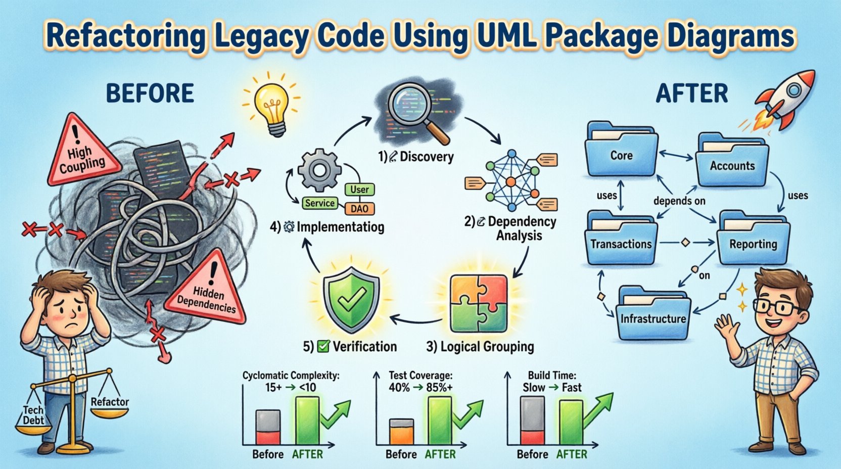
- High Coupling: Changes in one module frequently break unrelated modules.
- Low Cohesion: Classes contain responsibilities that do not belong together.
- Hidden Dependencies: Connections between components are implicit and difficult to trace.
- Documentation Gaps: Existing diagrams do not match the current code state.
Without a clear view of these issues, refactoring becomes a guessing game. This is where a UML package diagram becomes indispensable. It provides a high-level map of the system, allowing stakeholders to see the structure without reading every line of code.
The Role of UML Package Diagrams 📦
A UML package diagram is designed to organize elements of a system into groups. These groups, or packages, can represent modules, subsystems, or layers. Unlike a class diagram, which focuses on individual classes, a package diagram focuses on the relationships between larger units of code.
Key elements include:
- Packages: Containers for organizing classes and other packages.
- Dependencies: Arrows showing how one package uses another.
- Interfaces: Abstract definitions that packages implement or use.
- Imports: Mechanisms for exposing specific elements to other packages.
When applied to legacy code, the diagram acts as a reverse engineering artifact. It captures the current state, allowing teams to identify problematic patterns such as cyclic dependencies or deeply nested structures.
Case Study Context: The Financial Ledger System 💰
For this case study, consider a mid-sized financial application. The system manages transactions, user accounts, and reporting. Originally built as a monolithic application, it has grown over ten years. The codebase contains over 50,000 lines of code spread across hundreds of files. The database schema is tightly coupled with the application logic.
Current State Issues:
- The reporting module directly accesses database tables from the transaction module.
- Authentication logic is duplicated across multiple packages.
- There is no clear separation between business logic and data access.
The objective is to refactor this system to support microservices in the future. The immediate goal is to establish clear boundaries between modules. This requires creating a UML package diagram to visualize the intended structure.
Step-by-Step Refactoring Process 🛠️
The refactoring journey follows a structured methodology. Rushing into code changes without a plan often leads to regression. The process involves discovery, analysis, planning, execution, and verification.
1. Discovery and Extraction
The first step is to gather information about the existing system. This involves scanning the codebase for class definitions, method signatures, and file structures. Automated tools can assist in extracting this data, but human review is essential for context.
During this phase, the team creates an initial draft of the package diagram. This draft represents the physical structure rather than the logical structure. It shows where files are located rather than what they do. This distinction is crucial for identifying the gap between implementation and design.
2. Dependency Analysis
Once the physical structure is mapped, the team analyzes dependencies. They look for direct links between packages. A dependency exists if package A calls a method in package B.
Common dependency types found in legacy systems include:
| Dependency Type | Description | Refactoring Strategy |
|---|---|---|
| Direct | One package imports classes from another. | Introduce interfaces or dependency injection. |
| Cyclic | Package A depends on B, and B depends on A. | Extract common functionality to a shared package. |
| Deep Nesting | Multiple layers of packages call each other. | Flatten the hierarchy and establish clear layering. |
| Implicit | Dependencies exist through global state or static methods. | Encapsulate state and use explicit parameter passing. |
Identifying these dependencies allows the team to prioritize which areas to refactor first. Cyclic dependencies are often the most critical to resolve as they prevent independent testing and deployment.
3. Logical Grouping and Planning
With the dependency map in hand, the team designs the logical structure. This involves defining new packages based on business capabilities rather than technical implementation.
For the financial system, the logical packages might include:
- Core: Shared utilities and base classes.
- Accounts: Logic specific to user account management.
- Transactions: Logic for processing financial movements.
- Reporting: Logic for generating insights and summaries.
- Infrastructure: Database access and external service communication.
The plan documents how these packages will interact. It specifies which packages can depend on others. For example, the Reporting package should depend on the Transactions package, but not vice versa. This creates a directed acyclic graph of dependencies, which is easier to manage.
4. Implementation of Modularization
Refactoring begins with small, incremental changes. The team does not move the entire codebase at once. Instead, they focus on one package at a time.
Key actions during this phase include:
- Move Classes: Relocate classes to their new logical packages.
- Update Imports: Change file references to match the new structure.
- Introduce Interfaces: Define contracts for communication between packages.
- Remove Duplicates: Consolidate duplicated logic into the Core package.
Each change must be accompanied by tests. If the existing test suite does not cover the changed module, new tests must be written. This ensures that the refactoring does not break existing functionality.
5. Verification and Validation
After the code is moved, the team verifies the structure against the UML package diagram. They check that all dependencies match the planned architecture. They also run the full test suite to ensure behavioral consistency.
Validation involves:
- Static Analysis: Using tools to detect remaining cyclic dependencies.
- Code Review: Peer review to ensure naming conventions and structure are followed.
- Performance Testing: Ensuring the new structure does not introduce latency.
Once the diagram matches the code, the refactoring phase is considered complete for that module.
Managing Technical Debt During Refactoring ⚖️
Refactoring legacy code is not just about structure; it is about managing the cost of change. Every modification introduces risk. To mitigate this, the team must balance speed with safety.
Strategies for managing debt include:
- Feature Toggles: Hide new features behind flags until the refactoring is stable.
- Strangler Fig Pattern: Gradually replace old functionality with new modules.
- Continuous Integration: Run automated tests on every commit to catch regressions early.
- Documentation Updates: Keep the UML diagrams updated as the code changes.
It is vital to document the decision-making process. Future developers need to know why certain packages were created or why specific dependencies were avoided. This documentation becomes part of the knowledge base.
Common Pitfalls and How to Avoid Them ⚠️
Even with a solid plan, teams often encounter obstacles. Understanding these pitfalls helps in navigating the refactoring process smoothly.
Pitfall 1: Over-Engineering
There is a temptation to create a perfect architecture. While good design is important, perfectionism can stall progress. The goal is a structure that is maintainable, not one that is theoretically flawless.
Solution: Focus on the immediate problem. Add abstraction only when it is needed to resolve a specific coupling issue.
Pitfall 2: Ignoring Tests
Some teams skip writing tests during refactoring, assuming the code works. This is a high-risk strategy. If a bug is introduced, it may be difficult to trace.
Solution: Ensure 100% coverage for the modules being refactored. If coverage is low, write tests before moving code.
Pitfall 3: Inconsistent Naming
When moving code between packages, developers often keep old class names. This leads to confusion about where a class belongs.
Solution: Establish a naming convention early. For example, package names should match the domain concept, and class names should reflect their specific function.
Measuring Success 📊
How do you know the refactoring worked? Metrics provide objective evidence of improvement. The following indicators should be tracked before and after the project.
| Metric | Before Refactoring | After Refactoring |
|---|---|---|
| Cyclomatic Complexity | High (e.g., 15+) | Reduced (e.g., < 10) |
| Module Coupling | High (Many cross-deps) | Low (Layered structure) |
| Test Coverage | Low (e.g., 40%) | High (e.g., 85%+) |
| Build Time | Slow (Full rebuild) | Faster (Incremental builds) |
Tracking these metrics over time ensures that the improvements are sustained. If complexity creeps back up, it signals that the process needs reinforcement.
The Impact on Developer Productivity 🚀
Beyond technical metrics, refactoring has a human impact. Developers spend less time understanding code and more time building features. The cognitive load decreases when the architecture is clear.
Benefits include:
- Faster Onboarding: New team members can read the package diagram to understand the system.
- Reduced Bug Rates: Clear boundaries prevent unintended side effects.
- Confidence: Teams feel safer making changes when dependencies are visible.
This shift in culture is often the most valuable outcome of the project. It transforms the codebase from a liability into an asset.
Conclusion: Sustaining the Architecture 🔒
Refactoring legacy code using UML package diagrams is a disciplined process. It requires patience, planning, and a commitment to quality. By visualizing the structure, teams can identify risks and plan solutions that align with business goals.
The work does not end with the initial refactor. Architecture is a living thing. Regular reviews of the package diagrams ensure that the system evolves correctly. New features should be evaluated against the existing structure to prevent future debt.
Ultimately, the goal is a system that is easy to understand and easy to change. This state is achieved through consistent application of design principles and the continuous use of visual modeling tools. With a clear map in hand, the path forward becomes much easier to navigate.