


Designing complex software systems requires a structured approach to visualize relationships before implementation begins. The UML Package Diagram serves as a critical tool for architects and developers to organize code into manageable units. This guide explores how to utilize these diagrams for rapidly prototyping system structures, ensuring clarity and maintainability from the earliest stages of development. By focusing on namespaces and dependencies, teams can align on high-level architecture without getting lost in syntax details.
Understanding the Core Purpose of Package Diagrams 🧩
At its foundation, a UML Package Diagram is a structural diagram that organizes elements into groups. In the context of software engineering, these groups often represent modules, subsystems, or libraries. Unlike class diagrams which focus on individual attributes and methods, package diagrams provide a macroscopic view. This abstraction is essential when planning the skeleton of an application.
When prototyping system structure, the goal is not to define every method signature. Instead, the objective is to establish boundaries. These boundaries dictate how different parts of the system interact. Proper use of packages allows for:
- Namespace Management: Preventing naming conflicts between different modules.
- Logical Grouping: Clustering related functionality together for easier navigation.
- Dependency Visualization: Showing which components rely on others.
- Scalability Planning: Identifying where new features can be added without disrupting existing logic.
This high-level view is particularly valuable during the initial phases of a project. It allows stakeholders to review the flow of information and control before writing a single line of code. By establishing these structures early, teams reduce the risk of architectural debt accumulating over time.
Why Use Package Diagrams for Rapid Prototyping? 🛠️
Speed is a critical factor in modern development cycles. Rapid prototyping enables teams to test hypotheses about system design quickly. UML Package Diagrams are ideal for this because they are lightweight compared to detailed sequence or activity diagrams. They focus purely on static structure.
Here are the primary advantages of using package diagrams for prototyping:
- Reduced Cognitive Load: Stakeholders can grasp the system layout without needing deep technical knowledge of internal class implementations.
- Early Conflict Detection: Circular dependencies or tightly coupled modules become visible on the canvas immediately.
- Flexibility: It is easy to move packages around and see how the overall structure changes in real-time.
- Documentation Foundation: These diagrams often serve as the backbone for technical documentation, providing a map for future developers.
Using this method ensures that the system’s physical structure aligns with its logical design. It bridges the gap between abstract requirements and concrete implementation details.
Core Elements and Notation 📐
To model effectively, one must understand the standard notation used in these diagrams. While tools vary, the underlying semantics remain consistent across the industry. Below are the essential components you will encounter and utilize.
1. Packages
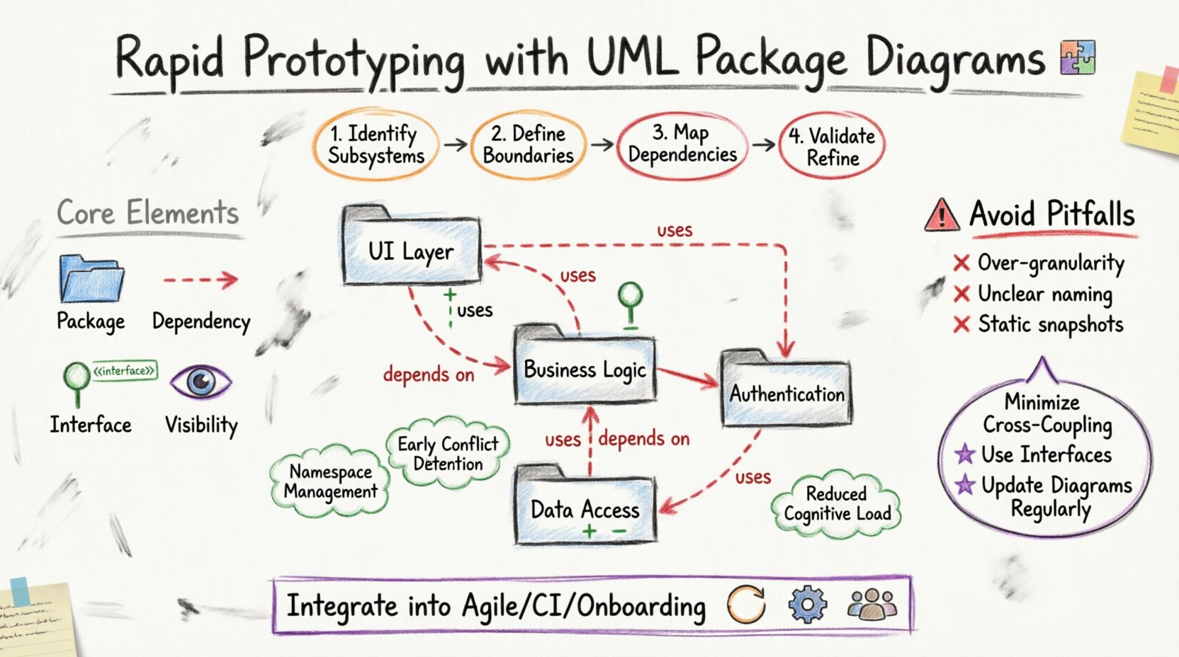
A package is represented by a folder icon. It acts as a namespace container. In a prototyping context, packages often correspond to layers of an application, such as Data Access, Business Logic, or User Interface. Naming conventions should be clear and descriptive.
2. Dependencies
Dependencies indicate that one package requires the contents of another to function. This is typically drawn as a dashed arrow. The arrow points from the dependent package to the package being used. This relationship implies a coupling that must be managed carefully.
3. Interfaces
Interfaces define contracts that packages must adhere to. They allow for loose coupling. In a diagram, an interface might be shown as a stereotype label or a small icon attached to a package boundary. This clarifies what functionality is exposed to other parts of the system.
4. Visibility
Visibility modifiers (Public, Private, Protected) apply to the elements inside packages. While often detailed in class diagrams, package-level visibility determines whether an entire module is accessible from outside its immediate context. This is crucial for security and encapsulation.
Step-by-Step Modeling Process 📝
Creating a robust prototype involves a systematic process. Rushing this stage can lead to confusing structures. Follow these steps to ensure a logical and scalable architecture.
Step 1: Identify Major Subsystems
Begin by listing the major functional areas of the application. These become your top-level packages. Ask yourself: What are the distinct responsibilities of this system? Examples might include Authentication, Reporting, and Transaction Processing. Group related requirements together.
Step 2: Define Boundaries
Once you have your top-level packages, determine their boundaries. Which functionality belongs inside, and what belongs outside? This step prevents scope creep during development. Ensure that each package has a single, clear responsibility.
Step 3: Map Dependencies
Draw arrows to show how packages interact. Be honest about these relationships. If Package A needs data from Package B, draw the dependency. This step reveals tight coupling. If you see too many arrows crossing between two layers, consider refactoring the design.
Step 4: Validate with Stakeholders
Before proceeding to detailed design, review the diagram with the team. Does this structure meet the business requirements? Are there any missing connections? Feedback at this stage is cheaper to implement than changes made during coding.
Step 5: Refine and Iterate
Prototyping is not a one-time event. As requirements evolve, the diagram should evolve with them. Update the structure to reflect new features or changes in logic. Keep the diagram synchronized with the codebase to maintain accuracy.
Managing Dependencies and Coupling 🔗
One of the most common challenges in system architecture is managing dependencies. Poorly managed dependencies lead to fragile systems where a change in one module breaks another. Package diagrams are the primary tool for visualizing and controlling this.
Consider the following strategies for dependency management:
- Minimize Cross-Coupling: Avoid direct dependencies between layers that should be independent. For example, the User Interface layer should not directly access the Database layer.
- Use Intermediate Layers: Introduce a service layer or adapter layer to mediate dependencies. This isolates changes.
- Reverse Dependencies: In some architectural patterns, like Hexagonal Architecture, dependencies point inward. Ensure your diagram reflects the intended direction of control.
- Interface Segregation: Do not expose entire packages. Define specific interfaces that packages implement. This reduces the surface area of coupling.
Visualizing these relationships helps teams identify circular dependencies early. A circular dependency occurs when Package A depends on Package B, and Package B depends on Package A. This creates a deadlock in compilation or execution and must be resolved.
Common Pitfalls and Best Practices ⚠️
Even experienced architects can make mistakes when modeling structure. Awareness of common pitfalls helps avoid them. Below is a checklist of best practices to maintain diagram integrity.
| Pitfall | Description | Solution |
|---|---|---|
| Over-Granularity | Creating too many small packages for minor components. | Group minor components into a single logical package. |
| Under-Abstraction | Showing internal classes instead of package boundaries. | Focus on modules, not individual classes. |
| Unclear Naming | Using generic names like ‘Module1’ or ‘System’. | Use descriptive names that reflect business logic. |
| Ignoring Visibility | Failing to mark internal vs. external packages. | Clearly define public interfaces and private internals. |
| Static Snapshots | Creating a diagram and never updating it. | Integrate diagram updates into the development workflow. |
By adhering to these practices, you ensure that the diagram remains a useful artifact throughout the project lifecycle. It should not become a relic of the past but a living document of the system’s evolution.
Integrating into the Development Lifecycle 🔄
Where does this modeling fit within the broader software development process? It is not a separate activity but an integrated part of design and planning. Here is how it aligns with common methodologies.
Agile and Iterative Development
In agile environments, architecture is emergent. However, having a baseline package structure helps guide the iteration. During sprint planning, teams can refer to the package diagram to ensure new features fit the existing boundaries. This prevents the architecture from drifting over time.
Continuous Integration
Automated tools can analyze the code structure against the package diagram. If a new module violates the defined dependencies, the build can fail. This enforces architectural rules automatically. It ensures that the code matches the design.
Onboarding New Developers
New team members often struggle to understand the system layout. A clear package diagram acts as an onboarding map. It shows them where to look for specific functionality and how the parts connect. This reduces the time to productivity.
Advanced Considerations for Large Systems 🏗️
As systems grow, a single diagram may become too crowded. Managing complexity requires advanced techniques.
- Sub-Packages: Break large packages into smaller sub-packages. This creates a hierarchy that can be navigated depth-first.
- Composite Diagrams: Use multiple diagrams to cover different views of the system. One diagram might show the high-level structure, while another details the internal dependencies of a specific subsystem.
- Linking Diagrams: Use references to link diagrams together. This maintains the overall context without overcrowding a single view.
- Documentation Integration: Embed the diagrams directly into the project documentation. This ensures they are always accessible alongside the code.
Conclusion on Structural Integrity ✅
Building a system structure using UML Package Diagrams is a disciplined approach to software design. It prioritizes organization, clarity, and maintainability. By focusing on namespaces and dependencies, teams can prototype effectively and make informed decisions before implementation begins. This process reduces risk and ensures that the final product is robust and scalable.
The effort invested in creating these diagrams pays dividends during the maintenance phase. When changes are required, the package structure provides a clear path forward. It highlights what can be changed safely and what requires caution. This foresight is what separates well-engineered software from fragile codebases.
Continue to refine your modeling skills. Treat the diagram as a contract between the design and the code. As long as the structure remains consistent, the system will remain adaptable to future needs.