
Mastering UML Sequence Diagrams: A Step-by-Step Guide to Modeling ATM Interactions
Welcome to this comprehensive tutorial on creating Sequence Diagrams in Unified Modeling Language (UML). Sequence diagrams are a critical component of the UML standard, designed to visually represent the interactions between objects within a system over time. Unlike static diagrams like Class diagrams, Sequence diagrams capture the dynamic behavior of a system, showing how messages are exchanged between participants to achieve a specific goal.
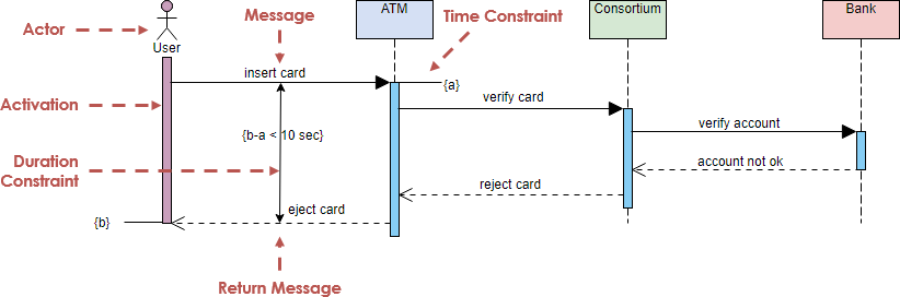
In this guide, we will deconstruct a classic banking scenario: the ATM withdrawal process. We will analyze the specific components, notations, and architectural patterns shown in the diagram below, providing you with the knowledge to model your own software systems effectively.
Understanding the Core Components
Before diving into the logic of the diagram, it is essential to understand the building blocks used to construct it. Every element in a sequence diagram serves a specific purpose in defining the flow of control and data.
1. Participants (Lifelines)
Participants represent the objects, classes, or external systems involved in the interaction. In our ATM example, we see four distinct participants:
- User (Actor): Represented by the stick figure, this is the human initiating the process.
- ATM (Object): The hardware and software system managing the transaction.
- Consortium: A third-party network or payment processor that validates the card.
- Bank: The financial institution’s core system responsible for account verification.
These participants are arranged horizontally at the top of the diagram. Below them extends a vertical dashed line known as a Lifeline, which represents the existence of the object over time.
2. Messages (Interactions)
Messages are the lines connecting the lifelines, representing communication between objects. The direction of the arrow indicates who is sending the message to whom.
- Sync Message (Solid Arrow): In the diagram, the “insert card” and “verify card” messages are solid lines with a filled arrowhead. This represents a synchronous call where the sender waits for a response before continuing.
- Return Message (Dashed Arrow): The “reject card” and “account not ok” messages are dashed lines. This typically indicates a return value or an asynchronous response flowing back up the hierarchy.
3. Activation Bars
The thin blue rectangles on the lifelines are called Activation Bars (or Focus of Control). They indicate the period during which an object is actively performing an action or waiting for a response. For instance, the ATM’s activation bar spans from the moment the user inserts the card until the card is ejected.
Decoding the Sequence Logic
Now, let’s walk through the specific interaction flow depicted in the diagram, which models a scenario where a card verification fails.
- Initiation: The process begins when the User performs the action
insert cardon the ATM. This triggers the ATM’s internal logic. - External Validation: The ATM must validate the card physically or logically. It sends a message
verify cardto the Consortium. Note the constraint{a}near this message, which might represent a specific condition or parameter. - Account Check: Upon receiving the request, the Consortium forwards the request to the Bank via the message
verify accountto check the user’s credentials. - Failure Response: The Bank determines the account is invalid (or the card is not recognized) and sends a
account not okresponse back to the Consortium. - Propagation of Error: The Consortium relays this failure back to the ATM with the message
reject card. - Termination: Finally, the ATM executes the action
eject cardand returns control to the User.
Advanced Notations: Constraints and Timing
Sequence diagrams are not just about “who talks to whom”; they are also about “when” and “how long.” The diagram includes specific annotations to handle temporal logic.
Time Constraints
Notice the text {Time Constraint} pointing to the Consortium lifeline. This indicates that the Consortium component has a specific time limit or requirement for handling the request. In high-security banking systems, ensuring that a response is returned within a specific window is critical to prevent timeouts or security vulnerabilities.
Duration Constraints
The diagram explicitly defines a time limit for the interaction between the User and the ATM. The annotation {b-a < 10 sec} between the activation bars signifies that the total duration (the difference between time ‘b’ and time ‘a’) must be less than 10 seconds. This is a crucial non-functional requirement, ensuring the system remains responsive.
Tooling: Visual Paradigm for UML
To bring these diagrams to life, you need robust modeling software. Visual Paradigm is a premier tool for creating UML diagrams, offering a user-friendly interface that simplifies complex modeling tasks.
Why Choose Visual Paradigm?
Visual Paradigm provides a comprehensive suite of features specifically designed for software architects and developers. Whether you are using the free version or the professional suite, it allows you to create sequence diagrams with precision.
Key Features for Sequence Diagrams
- Drag-and-Drop Interface: Easily add actors, objects, and messages by dragging them from the palette onto the diagram canvas.
- Auto-Alignment: The tool automatically aligns lifelines and activation bars, ensuring your diagram looks professional and adheres to standard UML spacing rules.
- Constraint Editors: Visual Paradigm allows you to define timing constraints (like the
{b-a < 10 sec}example) directly on the diagram, making your requirements explicit. - Code Generation: Once your sequence diagram is complete, Visual Paradigm can generate skeleton code in Java, C++, or C#, speeding up the development phase.
By mastering these concepts and utilizing tools like Visual Paradigm, you can create sequence diagrams that not only document your system but also serve as a blueprint for successful software development.