
Mastering UML Sequence Diagrams: A Step-by-Step Guide to Lifelines, Interactions, and Combined Fragments
UML Sequence Diagrams are one of the most powerful tools in a software architect’s arsenal. They visualize the dynamic behavior of a system over time, detailing exactly how objects interact to accomplish a specific task. While a static class diagram tells you what a system is composed of, a sequence diagram tells you how it works.
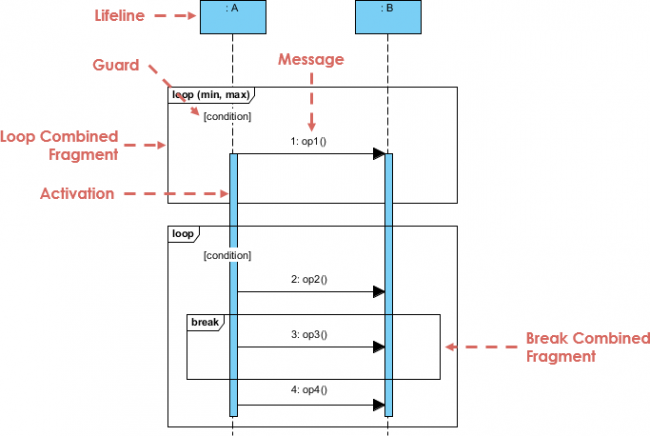
In this tutorial, we will break down the anatomy of a sequence diagram using the concepts illustrated in the provided example. We will explore the fundamental building blocks—Lifelines, Messages, and Activation Bars—and then dive deeper into the advanced control structures known as Combined Fragments.
1. The Foundation: Lifelines and Activation Bars
Every sequence diagram starts with the participants in the interaction. In our diagram, we see two primary participants: :A and :B.
- Lifeline: Represented by a vertical dashed line extending downward from the participant box, a lifeline signifies the existence of the object throughout the time frame of the diagram. It is the timeline upon which interactions occur.
- Activation Bar (Focus of Control): The thin blue rectangles drawn on the lifelines represent the period during which an object is performing an action. When object :A sends a message to :B, the activation bar on :B begins, indicating that :B is now busy processing that request.
2. The Action: Messages and Guards
The core of the diagram is the exchange of messages. These are depicted as horizontal arrows connecting the activation bars.
In the upper section of our diagram, we see a message labeled 1: op1(). This represents a method call or a signal sent from :A to :B. The label 1: indicates the sequence order of the message.
Guard Conditions: Notice the small box labeled [condition] pointing to the arrow. In UML, a guard condition is a boolean expression that determines if a message is sent. If the condition evaluates to true, the message is sent; if false, it is ignored. This allows the diagram to represent conditional logic (like an if statement) within the flow.
3. Advanced Control: Combined Fragments
Real-world systems rarely follow a straight line of execution. They involve loops, breaks, and alternative paths. UML handles this using Combined Fragments. These are rectangular frames with a specific operator in the top-left corner that dictate the control flow logic.
The Loop Fragment
One of the most common fragments is the loop operator. In the diagram, we see a large frame containing messages 1, 2, and 3. The operator loop (min, max) defines the iteration constraints. The [condition] inside the frame acts as the loop’s continuation condition. As long as the condition is true, the interactions inside the frame repeat.
The Break Fragment
Perhaps the most critical concept in the lower section of the diagram is the break operator. While a loop usually repeats indefinitely until the condition fails, a break operator allows the system to exit the loop early based on a specific condition.
In the example, we see a nested frame labeled break containing the message 3: op3(). This signifies that if the condition for the break is met, the system executes op3() and then immediately exits the enclosing loop, skipping any subsequent iterations or messages (such as 4: op4()) that follow.
Visual Hierarchy
Combined fragments are nested. The break fragment exists inside the loop frame. This nesting is crucial for understanding the logic: the break logic is only evaluated while the loop is active.
Summary of the Interaction Flow
Let’s synthesize the logic shown in the diagram:
- Start: Object :A initiates the interaction by sending
op1()to Object :B, provided the initial guard condition is met. - Looping: The system enters a loop. It repeatedly checks the loop condition.
- Iteration: Inside the loop, :A sends
op2()to :B. - Break Logic: Before proceeding to
op4(), the system checks thebreakcondition. If this condition is true, :A sendsop3()to :B, and the loop terminates immediately. - Completion: If the break condition is false, the loop continues, and :A sends
op4()to :B.
By mastering these components—Lifelines, Messages, and Combined Fragments—you can create sequence diagrams that are not just static pictures, but robust specifications of your system’s runtime logic.