


Software architecture relies heavily on clear documentation. When managing complex systems, selecting the right visualization tool is critical. The Unified Modeling Language (UML) offers various diagram types. Among them, the UML package diagram serves a distinct purpose. This guide explores specific scenarios for using package diagrams over class, component, or deployment diagrams. Understanding these distinctions prevents documentation clutter and ensures stakeholders grasp the system structure efficiently. 📋
Large-scale software projects involve thousands of classes, interfaces, and subsystems. Navigating this complexity requires abstraction. A single diagram cannot show every detail without becoming unreadable. The package diagram provides a high-level view of logical organization. It acts as a map for the codebase, grouping related elements into namespaces. This approach reduces cognitive load for developers and architects. 🧠
What is a UML Package Diagram? 📦
A UML package diagram is a structural diagram. It groups elements into packages. These packages represent logical groupings of model elements. They do not necessarily correspond to physical file structures, though they often align with module directories. The primary goal is to manage complexity through abstraction.
Key Characteristics
- Logical Grouping: Packages organize classes, interfaces, and other packages.
- Naming: Namespaces prevent naming conflicts between different parts of the system.
- Dependencies: Relationships indicate how packages rely on each other (e.g., import, use, realize).
- Visibility: They define public and private interfaces between groups.
Unlike detailed design diagrams, package diagrams focus on the macro structure. They answer the question: “Where does this feature belong?” rather than “How does this method work?”. This distinction is vital for maintaining a clear mental model of the application. 🗺️
Package Diagram vs. Class Diagram 🆚
The most common comparison is between package diagrams and class diagrams. Both are structural, but their scope differs significantly. Confusing the two leads to documentation that is either too granular or too abstract.
Scope and Detail
A class diagram describes the structure of individual classes. It lists attributes, operations, and relationships between specific classes. It is essential for developers writing code. However, in a system with 5,000 classes, a single class diagram becomes impossible to read.
A package diagram abstracts these classes. It treats a group of 100 classes as a single unit. This allows architects to see the flow of data between major subsystems without getting lost in implementation details.
When to Choose Each
- Use Class Diagrams When: You need to define the exact data structure of a specific domain entity. You are designing a database schema or API contract for a single module.
- Use Package Diagrams When: You are defining the overall project structure. You need to assign ownership of modules to different teams. You are planning a refactor of the namespace organization.
Using a class diagram for high-level architecture results in information overload. Using a package diagram for detailed coding specifications results in missing information. Balancing these two ensures clarity at every level of abstraction. ⚖️
Package Diagram vs. Component Diagram 🧩
Both package and component diagrams deal with system parts. However, they view those parts through different lenses: logical organization versus physical realization.
Logical vs. Physical
Package diagrams are logical. They represent the source code organization. A package might contain multiple classes that are compiled together, but the diagram focuses on the namespace.
Component diagrams are physical or runtime-focused. They represent deployable units, libraries, or executables. A component diagram answers: “What runs on the server?” or “What is the binary artifact?”.
Dependencies and Interfaces
In a package diagram, dependencies often represent import statements or method calls across namespaces. In a component diagram, dependencies represent runtime connections, such as API calls or database connections.
Decision Matrix
| Feature | Package Diagram | Component Diagram |
|---|---|---|
| Focus | Source Code Structure | Runtime Architecture |
| Granularity | Classes and Interfaces | Libraries and Executables |
| Relationships | Compilation Dependencies | Execution Dependencies |
| Stakeholders | Developers, Architects | DevOps, System Admins |
Choose the package diagram during the design phase to organize code. Choose the component diagram during the deployment planning phase to organize infrastructure. 🛠️
Package Diagram vs. Deployment Diagram 🌐
Deployment diagrams map the hardware and network topology. Package diagrams map the software logic. It is easy to conflate “where code lives” with “where code runs”, but they are distinct concerns.
Separation of Concerns
A package diagram remains valid regardless of the hardware. The same logical packages can be deployed on a monolithic server or distributed across microservices. The deployment diagram changes based on infrastructure choices. The package diagram changes based on business logic requirements.
Use Cases for Package Diagrams
- Microservices Planning: Defining which logical packages will eventually become which services.
- Legacy Refactoring: Visualizing how old modules map to new packages before moving data.
- Team Alignment: Ensuring Team A owns Package X and Team B owns Package Y to reduce merge conflicts.
If you draw a deployment diagram to show logical grouping, you limit flexibility. If you draw a package diagram to show server topology, you confuse the build process. Keep them separate for clarity. 🖥️
Package Diagram vs. Behavioral Diagrams ⚙️
Behavioral diagrams (like Sequence, Activity, or State diagrams) describe how the system behaves over time. Package diagrams describe what the system is made of. These two views are complementary but serve different questions.
Static vs. Dynamic
Package diagrams are static. They show the structure at a point in time. They do not show the flow of control or data movement during execution.
Behavioral diagrams are dynamic. They show the interaction between objects. They are necessary for understanding logic flow, but not for understanding code organization.
Integration in Documentation
Use package diagrams to define the boundaries. Use sequence diagrams to define the flow within those boundaries. For example, a package diagram might show a “Payment Service” package. A sequence diagram would then show the interaction between the “Payment Service” and the “Database” package.
Do not attempt to show logic flow in a package diagram. It is not designed for that purpose. Keep the structure separate from the behavior to maintain readability. 🔄
Best Practices for Package Diagrams ✨
Creating a package diagram is not just about drawing boxes. It requires adherence to architectural principles to remain useful.
1. Consistent Naming Conventions
- Use prefixes for namespaces (e.g.,
com.company.project). - Keep package names lowercase to avoid case sensitivity issues.
- Avoid abbreviations that are not universally understood.
2. Minimize Coupling
Dependencies between packages should be clear and minimal. If Package A depends on Package B, it should be explicit. High coupling between packages makes the system hard to refactor. Use the diagram to identify circular dependencies. 🚫
3. Layered Architecture
Organize packages by layer (e.g., Presentation, Business Logic, Data Access). This creates a visual hierarchy. It helps developers understand the flow of responsibility. Upper layers should not depend on lower layers directly.
4. Iterative Refinement
Start with broad packages. As the project grows, split large packages into smaller sub-packages. Do not try to create the final structure immediately. Evolve the diagram as the system evolves. 🌱
Common Pitfalls to Avoid ⚠️
Even experienced architects make mistakes when documenting structure. Awareness of these pitfalls helps maintain diagram quality.
Pitfall 1: Over-Engineering the Structure
Creating too many packages creates noise. If a package contains only one class, consider merging it. The goal is organization, not fragmentation.
Pitfall 2: Ignoring Dependencies
Drawings without dependency arrows are incomplete. Dependencies indicate the direction of control and data. Without them, the diagram is just a list of names.
Pitfall 3: Mixing Concerns
Do not mix physical file paths with logical packages. Do not mix database tables with application logic in the same package unless they are tightly coupled by design. Keep the separation of concerns visible in the diagram.
Conclusion 🏁
Selecting the right UML diagram type depends on the audience and the goal. The UML package diagram is the tool of choice for logical organization. It bridges the gap between high-level architecture and detailed code.
By distinguishing it from class, component, and deployment diagrams, teams can produce documentation that is both accurate and readable. Clear structure leads to maintainable software. Invest time in defining your packages correctly, and the benefits will persist throughout the lifecycle of the project. 🚀
Summary of Key Takeaways 📝
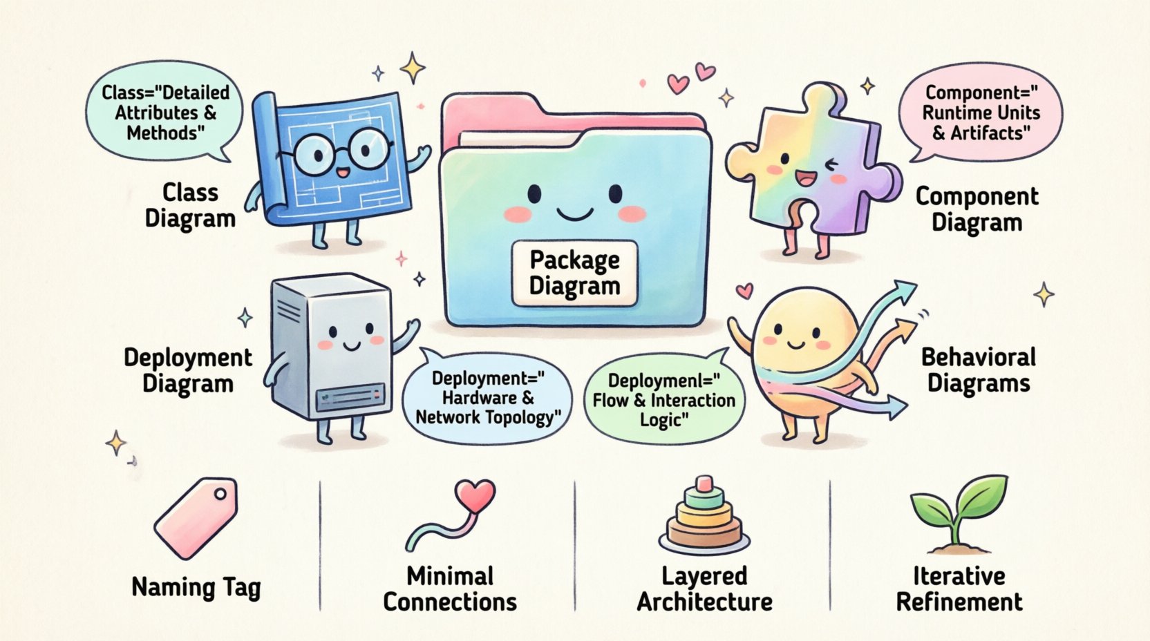
- Package Diagrams: Best for logical grouping and namespace management.
- Class Diagrams: Best for detailed class attributes and methods.
- Component Diagrams: Best for runtime units and deployment artifacts.
- Deployment Diagrams: Best for hardware and network topology.
- Behavioral Diagrams: Best for flow and interaction logic.
Use the package diagram to define the skeleton of your application. Let other diagrams flesh out the muscles and nerves of the system. This division of labor ensures a robust and understandable software architecture. 🏗️