


Building robust software requires a clear understanding of how different components interact with one another. When systems grow in complexity, visualizing these interactions becomes critical. Use Case Diagrams serve as a fundamental tool in this process, providing a high-level view of system functionality from the perspective of external actors. This guide explores the intricacies of modeling complex systems using this technique, focusing on structure, relationships, and best practices without relying on specific commercial tools.
Understanding the Foundation of System Modeling 🔍
Before diving into the mechanics of diagramming, it is essential to understand the purpose of modeling. Complex systems often involve multiple stakeholders, varying requirements, and intricate data flows. A Use Case Diagram acts as a bridge between business requirements and technical implementation. It captures what the system does, not necessarily how it does it.
- Abstraction: The model abstracts away implementation details to focus on functionality.
- Communication: It provides a common language for developers, analysts, and clients.
- Scope Definition: It clearly delineates what is inside the system boundary and what is outside.
When dealing with complex systems, the risk of ambiguity increases. A well-constructed diagram reduces this risk by forcing the team to define actors and goals explicitly. This section sets the stage for understanding the components that make up these diagrams.
Core Components of a Use Case Diagram 🧩
Every diagram consists of specific elements. Understanding the definition and behavior of each element is crucial for accurate modeling. There are three primary components to consider when constructing these visuals.
1. Actors 👤
An actor represents a role played by an entity that interacts with the system. Actors can be people, other systems, or hardware devices. It is important to distinguish between the role and the individual. For example, a “Manager” is an actor, while “John Doe” is an instance of that actor.
- Internal Actors: Systems or processes within the same environment that trigger actions.
- External Actors: Users or third-party systems that exist outside the system boundary.
- Primary vs. Secondary: Primary actors initiate the use case; secondary actors support the process.
2. Use Cases ⚙️
A use case represents a specific goal or function that an actor wants to achieve. It is a complete unit of functionality. In complex systems, use cases can be numerous, requiring careful organization.
- Goal-Oriented: Each use case must result in a valuable state change or outcome.
- Granularity: Use cases should be neither too broad (e.g., “Manage System”) nor too narrow (e.g., “Click Button”).
- Scope: They must fall within the defined system boundary.
3. System Boundary 📦
The system boundary is a rectangle that encloses all use cases. Everything outside this box is external to the system. This visual cue helps stakeholders understand what the current project will deliver and what relies on external factors.
- Clear Delineation: Anything not inside the box is assumed to be an external dependency.
- Interface Definition: The boundary represents the interface between the system and its environment.
Defining Relationships and Interactions 🔗
Connections between elements define the flow of control. There are specific relationship types that must be understood to model logic correctly. Misusing these relationships can lead to confusion during development.
Association
The association line connects an actor to a use case. It indicates that the actor interacts with that specific functionality. This is the most basic relationship.
- Direction: While often drawn as a line, interaction usually flows from the actor to the use case.
- Multiplicity: An actor can participate in multiple use cases, and a use case can involve multiple actors.
Include Relationship
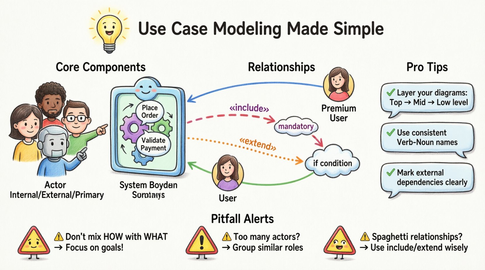
The include relationship indicates that one use case incorporates the behavior of another. This is used for mandatory behavior that is reused across multiple scenarios.
- Mandatory: The included use case must happen for the base use case to complete.
- Refinement: It helps break down complex use cases into smaller, manageable chunks.
- Example: “Place Order” might include “Validate Payment” as a mandatory step.
Extend Relationship
The extend relationship indicates optional behavior. A use case can extend another at a specific point if a certain condition is met.
- Optional: The extended behavior is not required for the base use case to succeed.
- Trigger: It depends on a specific condition being true.
- Example: “Place Order” might be extended by “Apply Discount” if the user is a member.
Generalization
Generalization represents inheritance. An actor can be specialized into a more specific actor, or a use case can be specialized into a more specific use case.
- Actor Inheritance: A “Premium User” is a specialized version of a “User”.
- Use Case Inheritance: A specific action inherits the logic of a broader action.
- Polymorphism: Allows the system to handle different types of inputs differently while maintaining a consistent interface.
Strategies for Handling System Complexity 🧠
As systems grow, diagrams can become cluttered and unreadable. To maintain clarity, specific strategies must be employed. These techniques help manage the scale of the model without losing detail.
1. Abstraction and Hierarchy
Do not attempt to model every single detail in one diagram. Use packages or subsystems to group related use cases. This creates a hierarchy where high-level diagrams show major functions, and lower-level diagrams detail the specifics.
- Top-Level: Show primary goals and major actors.
- Mid-Level: Break down major goals into sub-goals.
- Low-Level: Detail specific interactions for complex processes.
2. Standardizing Terminology
Consistency in naming is vital. If a use case is called “Login” in one diagram, it should not be “Sign In” in another. A shared glossary helps maintain this consistency across the documentation.
- Verb-Noun Structure: Use consistent patterns like “Manage User” or “View Report”.
- Actor Naming: Use role-based names rather than specific names.
3. Managing Dependencies
Complex systems often rely on external services. Clearly mark these dependencies. Use separate diagrams for external system interactions if the complexity warrants it.
- Explicit Interfaces: Define how the system talks to external actors.
- Separation of Concerns: Keep business logic separate from infrastructure logic in the modeling.
Common Pitfalls and How to Avoid Them ⚠️
Even experienced analysts make mistakes when modeling. Identifying these pitfalls early saves significant rework later. The table below outlines common errors and their corrections.
| Pitfall | Impact | Correction Strategy |
|---|---|---|
| Mixing Implementation with Function | Confuses stakeholders about what the system does vs. how it works | Focus on goals. Remove technical steps like “Click Save”. |
| Too Many Actors | Clutters the diagram and dilutes focus | Group similar roles or create specialized actors only if behavior differs. |
| Unclear System Boundary | Leads to scope creep and ambiguity | Draw a clear box. Anything outside is external. |
| Overusing Include/Extend | Creates spaghetti logic that is hard to trace | Use only for truly mandatory (include) or conditional (extend) logic. |
| Missing Actors | Functionality exists without a trigger | Review every use case to ensure an actor initiates it. |
Validation and Verification Processes ✅
Once the diagram is drafted, it must be validated. Verification ensures the model is accurate; validation ensures it meets user needs. This process involves rigorous review.
- Walkthroughs: Walk through scenarios with stakeholders to ensure flow makes sense.
- Consistency Checks: Verify that included use cases exist and are correctly referenced.
- Completeness Review: Ensure no major functionality is left out of the scope.
- Traceability: Map use cases back to specific business requirements.
Validation is not a one-time event. As requirements evolve, the diagram must be updated. Maintaining version control for these models is essential for tracking changes over time.
Integrating Use Cases with Broader Documentation 📝
A diagram alone is rarely sufficient. It must be supported by textual descriptions and other artifacts. This integration ensures that the visual model is fully understood.
Use Case Descriptions
Each use case should have a corresponding text description. This document outlines the flow of events, preconditions, postconditions, and exceptions.
- Preconditions: What must be true before the use case starts?
- Basic Flow: The primary path to success.
- Alternative Flows: Variations of the basic flow.
- Exceptions: What happens if things go wrong?
Alignment with Requirements
Use cases serve as a bridge to the requirements specification. Every requirement should map to at least one use case. Conversely, every use case should trace back to a business goal.
- Traceability Matrix: Create a matrix linking requirements to use cases.
- Gap Analysis: Identify requirements without use cases or vice versa.
Supporting Technical Design
While Use Case Diagrams are high-level, they inform lower-level design. They help identify classes, interfaces, and state machines.
- Domain Objects: Use cases often reveal key entities in the system.
- Interface Contracts: Actor interactions define API contracts.
- Test Cases: Use case flows form the basis for acceptance testing.
Conclusion of the Modeling Process
Modeling complex systems with Use Cases is a disciplined activity. It requires a clear understanding of actors, goals, and boundaries. By following the strategies outlined here, teams can create diagrams that are accurate, maintainable, and useful for communication. The goal is not just to draw a picture, but to understand the system deeply enough to build it correctly.
Remember that the diagram is a living artifact. It evolves as the system evolves. Continuous review and validation ensure that the model remains a reliable source of truth throughout the project lifecycle. With careful attention to relationships and complexity management, these diagrams become powerful tools for system analysis and design.