


In the landscape of modern system design, the use case diagram remains a cornerstone for visualizing interactions. While often associated with traditional software development lifecycles, these diagrams offer significant value in contemporary engineering contexts. From cloud-native architectures to distributed microservices, the ability to map user goals against system capabilities is critical. This guide explores how to apply use case modeling effectively today, focusing on clarity, collaboration, and adaptability without relying on specific proprietary tools.
Engineering teams today face complexity that was unimaginable a decade ago. The systems are not monolithic; they are fluid, interconnected, and often distributed across various environments. A static representation of functionality can quickly become obsolete if not managed with the right strategies. By adopting innovative approaches, engineers can maintain the integrity of their models while ensuring they remain relevant to the evolving architecture.
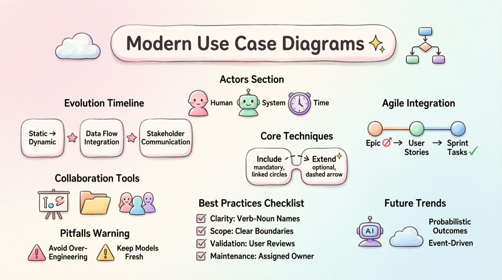
Evolution of Modeling Standards 📜
The foundational principles of use case modeling have remained stable, but the application has shifted. Originally designed for requirements gathering in waterfall methodologies, these diagrams now serve as living documents in iterative environments. The shift is not merely about the diagram itself but how it integrates with the broader documentation strategy.
- From Static to Dynamic: Early models often captured a snapshot of requirements. Modern approaches treat them as evolving artifacts that change alongside the system.
- Integration with Data Flows: Contemporary engineering demands that functional requirements align with data movement. Use cases now often reference data stores and API endpoints implicitly.
- Stakeholder Communication: The primary audience has expanded beyond developers to include product owners, QA engineers, and security auditors. The visual language must be accessible to all.
Understanding this evolution helps teams avoid the trap of treating diagrams as mere documentation artifacts. They are communication tools that bridge the gap between abstract business goals and concrete technical implementation.
Core Principles in Modern Context 🧠
To utilize these diagrams effectively in current projects, one must adhere to core principles that ensure utility. Ambiguity is the enemy of engineering precision. Every actor and every use case must be defined with specific boundaries.
Defining Actors in Distributed Systems 🤖
In legacy systems, an actor might simply be a human user. In contemporary engineering, actors often include external systems, automated scripts, or third-party services. Identifying these correctly is vital.
- Human Actors: The end-users interacting with the interface directly.
- System Actors: Other software applications or services that initiate interactions via API calls.
- Time Actors: Scheduled tasks or cron jobs that trigger processes without human intervention.
When mapping these actors, ensure that the distinction between internal and external interactions is clear. This prevents scope creep during development and ensures that security boundaries are respected from the initial design phase.
Use Case Granularity 🧩
One common challenge is determining the right level of detail. If a use case is too broad, it lacks actionable information for developers. If it is too narrow, the diagram becomes cluttered and difficult to read.
A balanced approach involves breaking down complex processes into sub-flows or including them as secondary use cases. This keeps the main diagram clean while preserving the necessary detail in the supporting documentation.
Advanced Techniques for Complex Architectures 🛠️
As systems grow in complexity, standard diagrams may require augmentation. Engineers can employ specific techniques to handle scenarios involving multiple environments or high-volume data processing.
Inclusion and Extension Points 🔄
The relationships of include and extend are powerful tools for managing complexity.
- Include: Use this to represent mandatory behavior that is common across multiple use cases. For example, “Authenticate User” might be included in “Login”, “Reset Password”, and “Change Profile”.
- Extend: Use this for optional behavior that occurs under specific conditions. For instance, “Apply Discount Code” extends “Complete Purchase” only if a code is provided.
State Management Considerations ⏳
While use case diagrams do not show state transitions directly, they imply them. In modern engineering, understanding the state of an object during an interaction is crucial. Engineers should annotate use cases to indicate expected state changes or prerequisites.
This ensures that developers understand not just what the user wants to do, but the state of the system required to perform the action. It reduces errors related to race conditions or invalid state transitions.
Integration with Agile and DevOps 🚀
The relationship between use case diagrams and agile methodologies is often misunderstood. Some view them as too rigid for iterative development. However, when adapted correctly, they provide stability amidst change.
Epics and User Stories 📝
In agile frameworks, use cases often serve as epics. They group related user stories together. This allows teams to visualize the broader goal while breaking it down into sprint-sized tasks.
- Visual Backlog: The diagram can act as a visual backlog, helping product owners prioritize features based on user goals rather than technical tasks.
- Definition of Done: A use case provides a clear criteria for completion. The interaction is successful, and the system state reflects the expected outcome.
Continuous Modeling in CI/CD 🔄
In DevOps pipelines, documentation should not be a bottleneck. Models should be updated as part of the deployment process. If a feature is added, the diagram should reflect that change. This keeps the documentation synchronized with the codebase.
Automation tools can assist in verifying that the implementation matches the model, though the responsibility lies with the engineering team to maintain the source of truth.
Collaborative Modeling Strategies 🤝
Engineering is rarely a solitary activity. Collaborative modeling ensures that everyone involved has a shared understanding of the system. This reduces miscommunication and rework later in the cycle.
Workshops and Live Sessions 🗣️
Instead of sending diagrams via email, hold workshops where stakeholders can draw and refine the models together. This encourages immediate feedback and alignment.
- Whiteboarding: Physical or digital whiteboards allow for rapid iteration during meetings.
- Real-time Editing: Teams can update diagrams live during sprint planning to ensure the scope is accurate.
Version Control for Models 📂
Just as code is versioned, models should be treated as versioned assets. This allows teams to track changes over time and revert if a direction proves unviable.
Commit messages should explain why a use case was added or removed. This creates an audit trail that is invaluable for future maintenance and onboarding new team members.
Comparative Analysis of Approaches 📋
To better understand where to focus efforts, it is helpful to compare traditional methods with contemporary adaptations.
| Feature | Traditional Approach | Contemporary Approach |
|---|---|---|
| Focus | Requirements Documentation | Communication & Validation |
| Lifecycle | Waterfall (Static) | Agile (Iterative) |
| Actors | Primarily Human | Human, System, Service |
| Integration | Separate Documentation | Linked to Code & API Specs |
| Update Frequency | Phase Gates | Continuous / Sprint-based |
This table highlights the shift from documentation as an end-product to documentation as a process tool. The contemporary approach prioritizes alignment and adaptability.
Common Pitfalls to Avoid ⚠️
Even with the best intentions, teams can fall into traps that reduce the value of their diagrams. Recognizing these pitfalls early helps maintain model quality.
- Over-Engineering: Creating diagrams that are too complex for the team to maintain. Keep the visual simple.
- Ignoring Non-Functional Requirements: A use case describes functionality, but performance, security, and reliability are equally important. Ensure these are noted separately or linked.
- Stale Models: Updating the code but forgetting the diagram. This leads to a disconnect between what is built and what is documented.
- Too Many Actors: If a diagram has too many actors, it becomes unreadable. Group related actors or simplify the scope.
Best Practices Summary 📌
| Area | Recommendation |
|---|---|
| Clarity | Use verb-noun phrases for use case names (e.g., “Submit Order”, not “Submitting”). |
| Scope | Define the system boundary clearly to distinguish internal vs. external behavior. |
| Validation | Review diagrams with actual end-users to ensure they match real-world expectations. |
| Maintenance | Assign ownership of the diagram to a specific role, such as a System Architect. |
Future Trends and Adaptability 🌐
The landscape of engineering continues to shift. Artificial intelligence and machine learning are becoming integrated into almost every system. How does a use case diagram handle an AI-driven feature?
Handling AI Interactions 🤖
When a system uses machine learning, the interaction is probabilistic. A use case might describe “Predict User Intent” rather than a deterministic action. The diagram should reflect the variability in outcomes.
Consider annotating use cases with confidence levels or data dependencies. This helps stakeholders understand the limitations of the system.
Cloud-Native Considerations ☁️
Cloud-native architectures rely heavily on serverless functions and event streams. Use cases should map to events rather than just user clicks. For example, “Order Placed” is an event that triggers multiple downstream processes.
This perspective ensures that the diagram captures the event-driven nature of modern infrastructure.
Final Thoughts on Implementation 🏁
Implementing these innovative approaches requires a commitment to discipline and clarity. The goal is not to produce a diagram that looks perfect, but one that serves the team effectively. By treating use case diagrams as dynamic communication tools rather than static artifacts, engineering teams can navigate the complexities of contemporary systems with greater confidence.
Focus on the value the diagram provides to the stakeholders. If it helps developers build correctly, helps testers verify thoroughly, and helps managers understand the scope, it is succeeding. Regular reviews and updates ensure that the model remains a reliable guide through the development lifecycle.
As you move forward, prioritize understanding the interactions between your system and its environment. The connections are often more critical than the internal details. By mastering the art of mapping these interactions, you contribute to building robust, maintainable, and user-centric engineering solutions.
Remember that the diagram is a means to an end, not the end itself. Use it to facilitate discussion, validate assumptions, and align expectations. When done well, it becomes an integral part of the engineering culture, supporting the delivery of high-quality systems in a complex world.